Pneumatic tire
a pneumatic tire and tire side technology, applied in the field of pneumatic tires, can solve the problems of degrading the stability of steering, degrading the ride quality and the like, and the temperature rise in the side portions of the tire cannot be sufficiently suppressed, so as to achieve the effect of reducing the temperature rise and improving the durability of the tir
- Summary
- Abstract
- Description
- Claims
- Application Information
AI Technical Summary
Benefits of technology
Problems solved by technology
Method used
Image
Examples
first embodiment
Modification 6
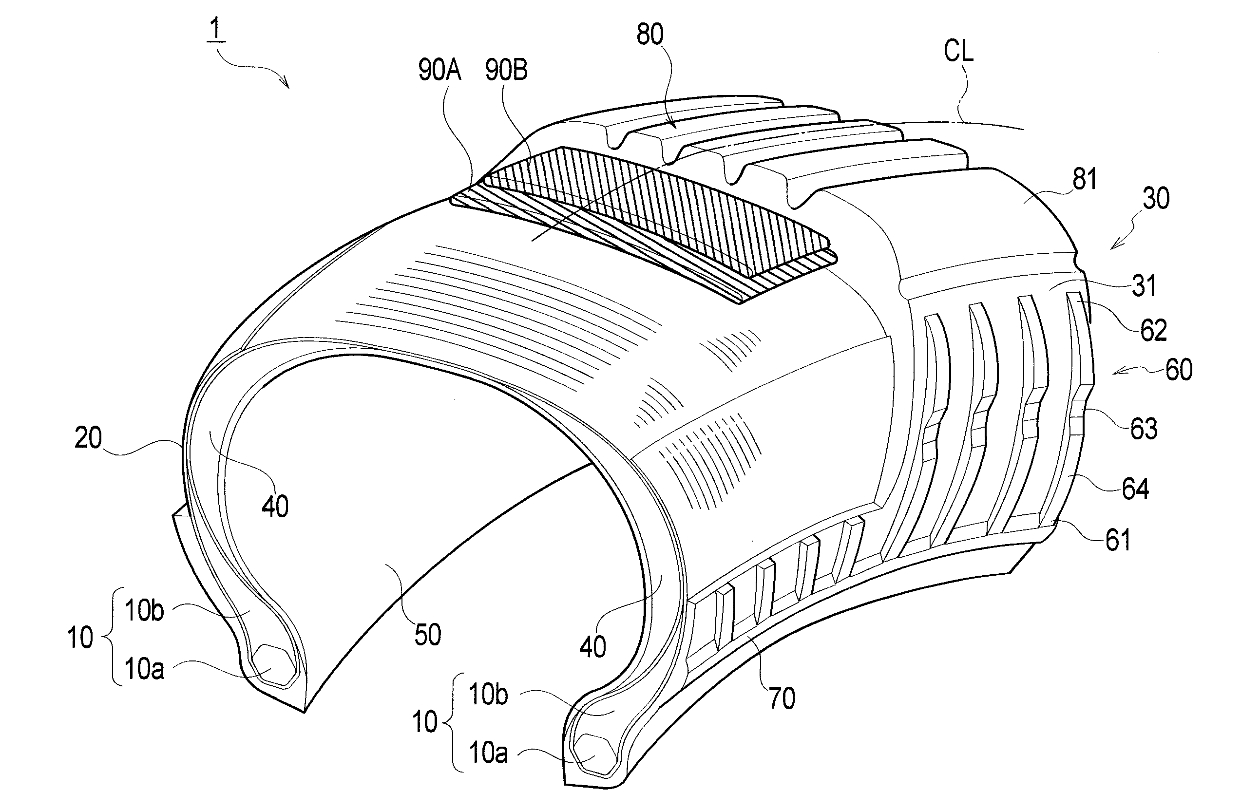
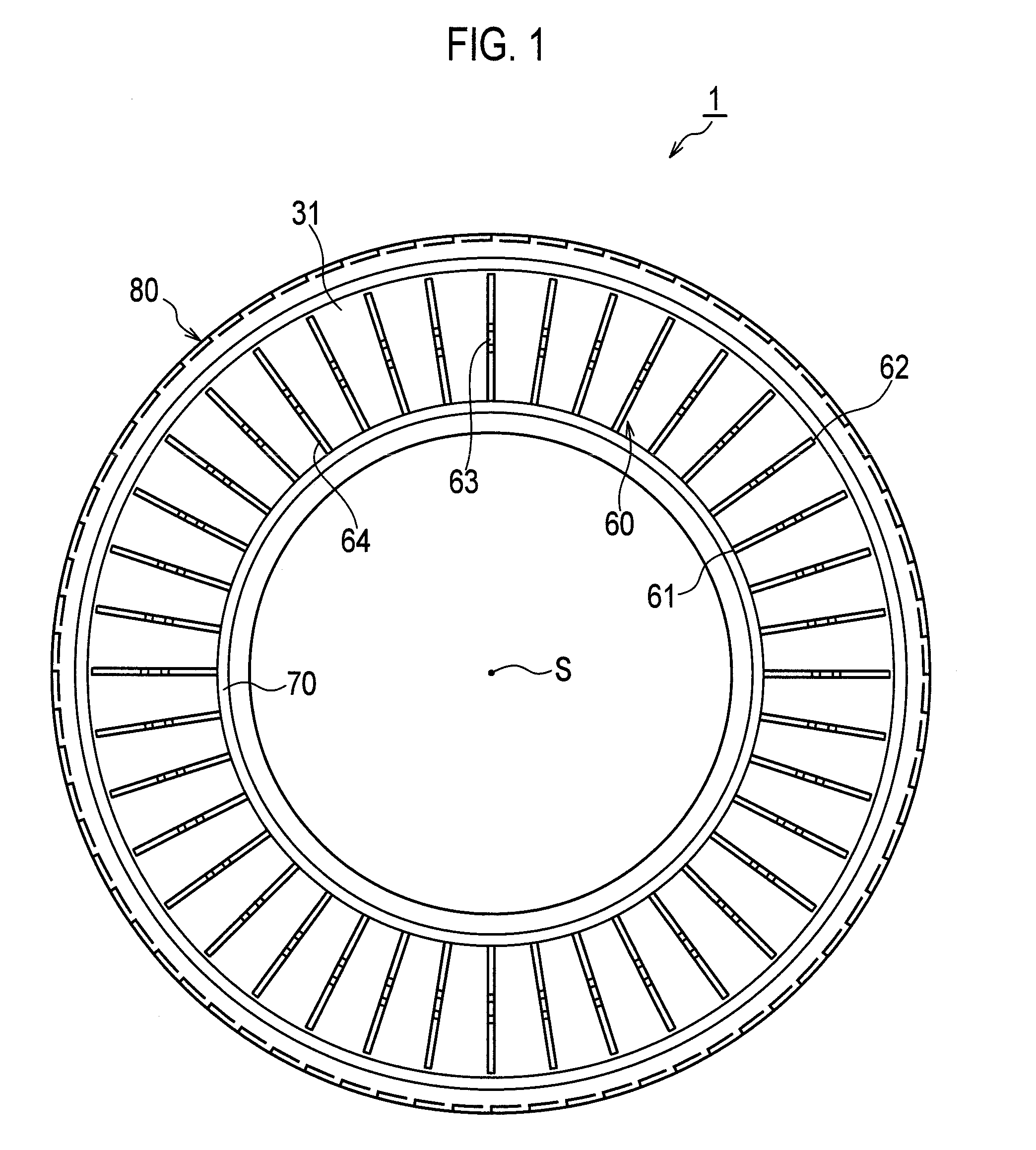
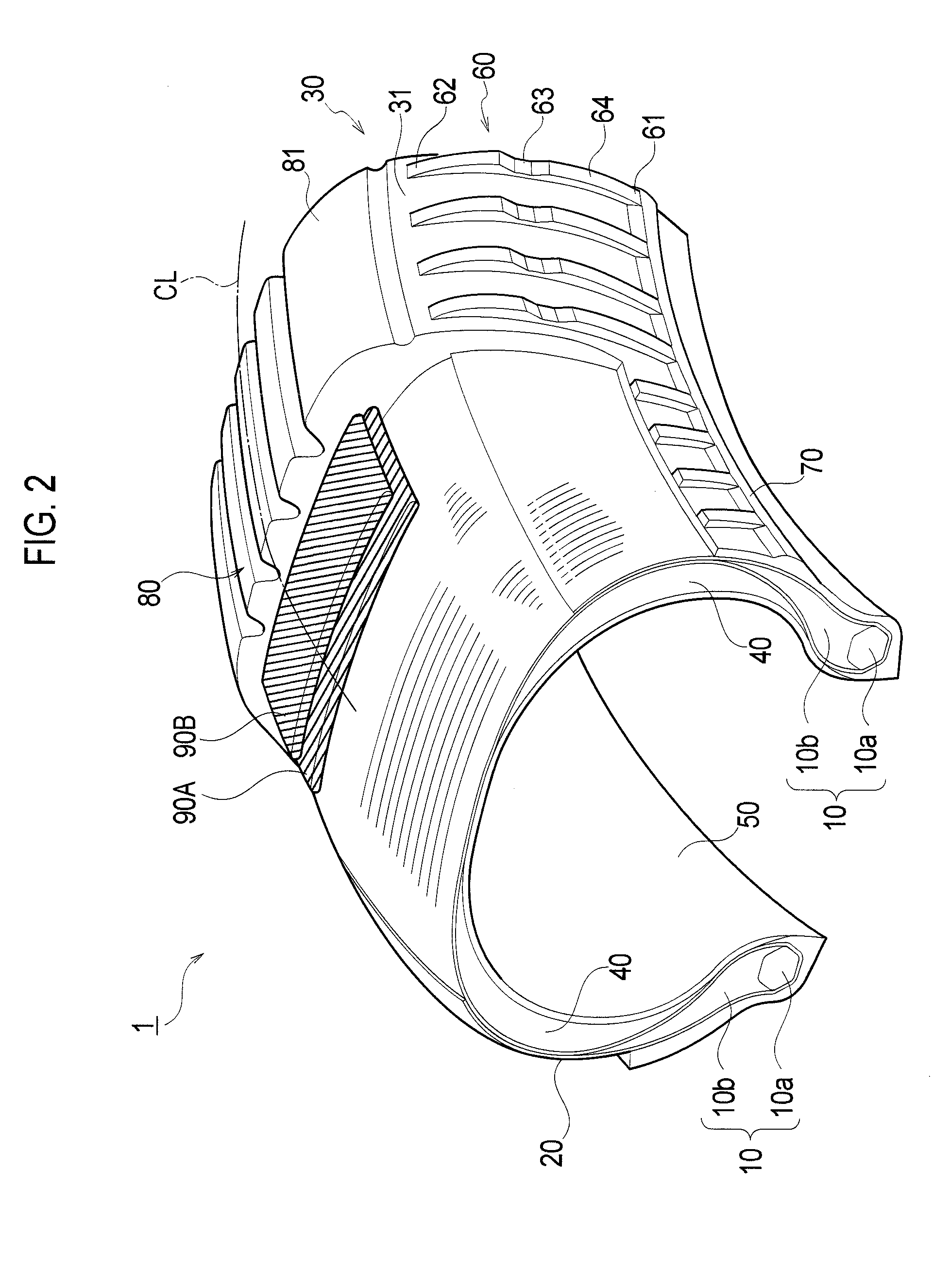
[0119]In the above description, the radial-protrusions 60 according to the first embodiment extend straight in the tire radial direction. However, the following modification may be made. The same portions as those of the pneumatic tire 1 according to the first embodiment are denoted by the same reference signs. Different portions are mainly described.
[0120]FIG. 15 is a side view of a pneumatic tire according to Modification 6. As FIG. 15 shows, the radial protrusions 60 each curve with respect to the tire radial direction. In other words, the extending-direction angle (θ) largely changes from an inner side, in the tire radial direction, of the protrusion 60 to an outer side, in the tire radial direction, of the protrusion 60.
[0121]The extending-direction angle (θ) does not necessarily have to largely change from the inner side in the tire radial direction to the outer side in the tire radial direction. The extending-direction angle (θ) may slightly change from the inne...
second embodiment
Modification 3
[0142]In the above description, the radial-protrusions 60 according to the second embodiment extend straight in the tire radial direction. However, the following modification may be made. The same portions as those of the pneumatic tire 1 according to the second embodiment are denoted by the same reference signs. Different portions are mainly described.
[0143]FIG. 21 is a side view of a pneumatic tire according to Modification 3. As FIG. 21 shows, the radial protrusions 60 curve with respect to the tire radial direction. In other words, the extending-direction angle (θ) largely changes from an inner side, in the tire radial direction, of the protrusion 60 to an outer side, in the tire radial direction, of the protrusion 60.
[0144]The extending-direction angle (θ) does not necessarily have to largely change from the inner side in the tire radial direction to the outer side in the tire radial direction. The extending-direction angle (θ) may slightly change from the inner s...
examples
[0152]Next, to further clarify the effects of the present invention, results of tests conducted using pneumatic tires according to Comparative Examples and Examples below are described. The present invention is not limited whatsoever by these examples. Data on each pneumatic tire are measured under the following conditions.
[0153]Tire Size: 285 / 50R20
[0154]Wheel Size: 8JJ×20
[0155]Internal Pressure Condition: 0 kPa (flat)
[0156]Load Condition: 9.8 kN
[0157]Speed Condition: 90 km / h
[0158]The configuration and a test result (durability) of each pneumatic tire are described with reference to Tables 1 to 3.
TABLE 1ComparativeComparativeComparativeparameterExample 1Example 2Example 3p / hwithout1515(p − w) / wprotrusions2929w(mm)22h(mm)22hs(mm)22hs / h (index)11B(mm)——continuous portion——in circumferentialdirectiondurability(index)6510098
TABLE 2Exam-Exam-Exam-Exam-Exam-parameterple 1ple 2ple 3ple 4ple 5p / h←←←←←(p − w) / w←←←←←w(mm)←←←←←h(mm)←←←←←hs(mm)1.81.61.00.40.2hs / h (index)0.90.80.50.20.1B(mm)8←←←...
PUM
 Abstract
Description
Claims
Application Information
 - R&D
- Intellectual Property
- Life Sciences
- Materials
- Tech Scout
- Unparalleled Data Quality
- Higher Quality Content
- 60% Fewer Hallucinations
Browse by: Latest US Patents, China's latest patents, Technical Efficacy Thesaurus, Application Domain, Technology Topic, Popular Technical Reports.
© 2025 PatSnap. All rights reserved.Legal|Privacy policy|Modern Slavery Act Transparency Statement|Sitemap|About US| Contact US: help@patsnap.com


