Header Plate And Heat Exchanger Comprising Same

a technology of header plates and heat exchangers, which is applied in the direction of heat exchange apparatus, machines/engines, light and heating equipment, etc., can solve the problems of no extra means for facilitating the attachment of air tubes to the header plates, and achieve the effects of high durability, high flow resistance and compact design

Inactive Publication Date: 2011-04-21
VALEO SYST THERMIQUES
View PDF16 Cites 2 Cited by
  • Summary
  • Abstract
  • Description
  • Claims
  • Application Information

AI Technical Summary

Benefits of technology

[0008]According to a further embodiment the rims of said apertures and said flanges protrude on the same side of the header plate, wherein the distance between an inner face of either flange and apertures adjacent to said inner face is less than three times the thickness of the header plate sheet metal. This solution is favourable especially when housing walls of about the same thickness as the header plate are arranged inside of said flanges, making it possible to use the same kind of turbulating means between the air tubes as such and between said housing walls and the adjacent air tubes.
[0009]In the further embodiment insertion spaces are preferably provided between said flanges and rims of adjacent apertures for receiving edge portions of casing walls. In that way assembly of a unit in which a header plate according to the invention is included can be simplified.
[0010]It is obvious to the person skilled that it is advantageous if the header plate and the air tubes are clad and pre-fluxed in order to be brazeable in an oven after insertion of the air tubes into said apertures.
[0011]According to another embodiment of the invention a heat exchanger is provided, comprising a coolant housing passed by a plurality of air tubes, wherein air tubes are inserted in and attached to rimmed

Problems solved by technology

However, there are no extra means for facilitating the attachment of the air tubes to the header plates and to ensure tightness between these parts ot

Method used


Image

  • Header Plate And Heat Exchanger Comprising Same
  • Header Plate And Heat Exchanger Comprising Same
  • Header Plate And Heat Exchanger Comprising Same

Examples


Embodiment Construction

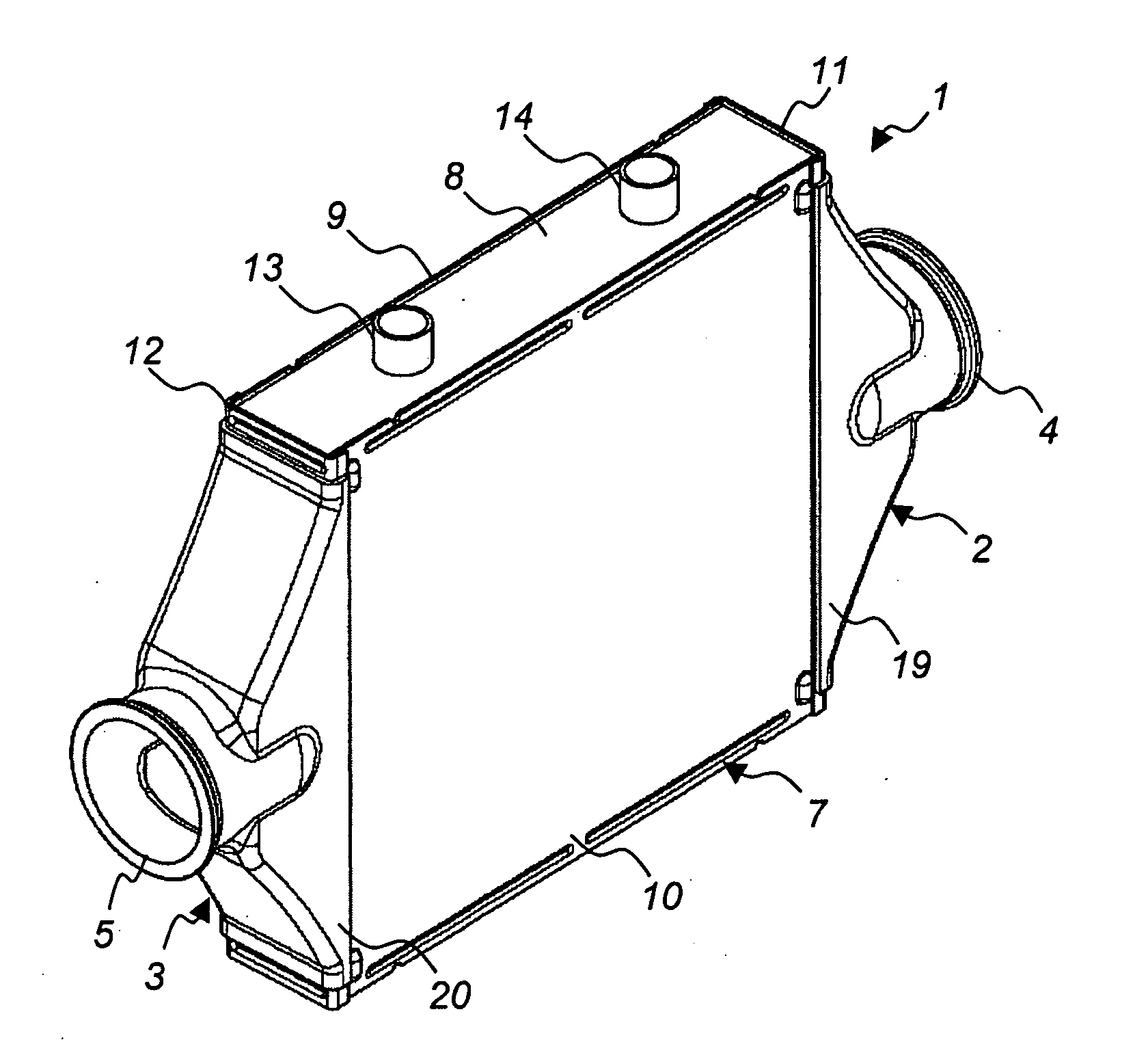
[0023]The heat exchanger 1 shown in FIG. 1 is a so called WCCAC, which stand for Water Cooled Charge Air Cooler. It is used to cool charge air led to an engine intake with the aid of a coolant mainly comprising water. The coolant is usually shared with the engine as such, which renders it possible to use the engine cooling radiator to cool the WCCAC as well.

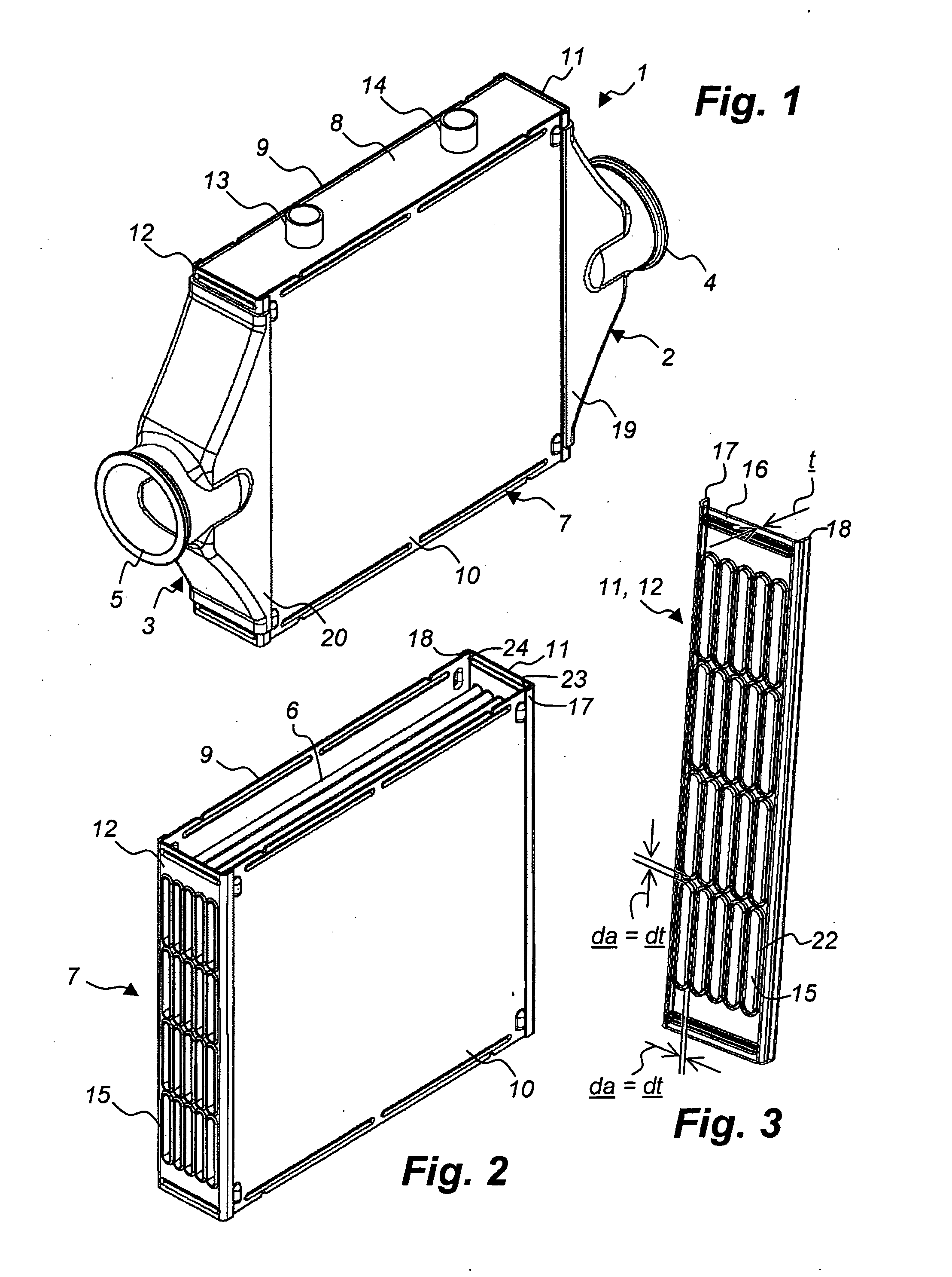
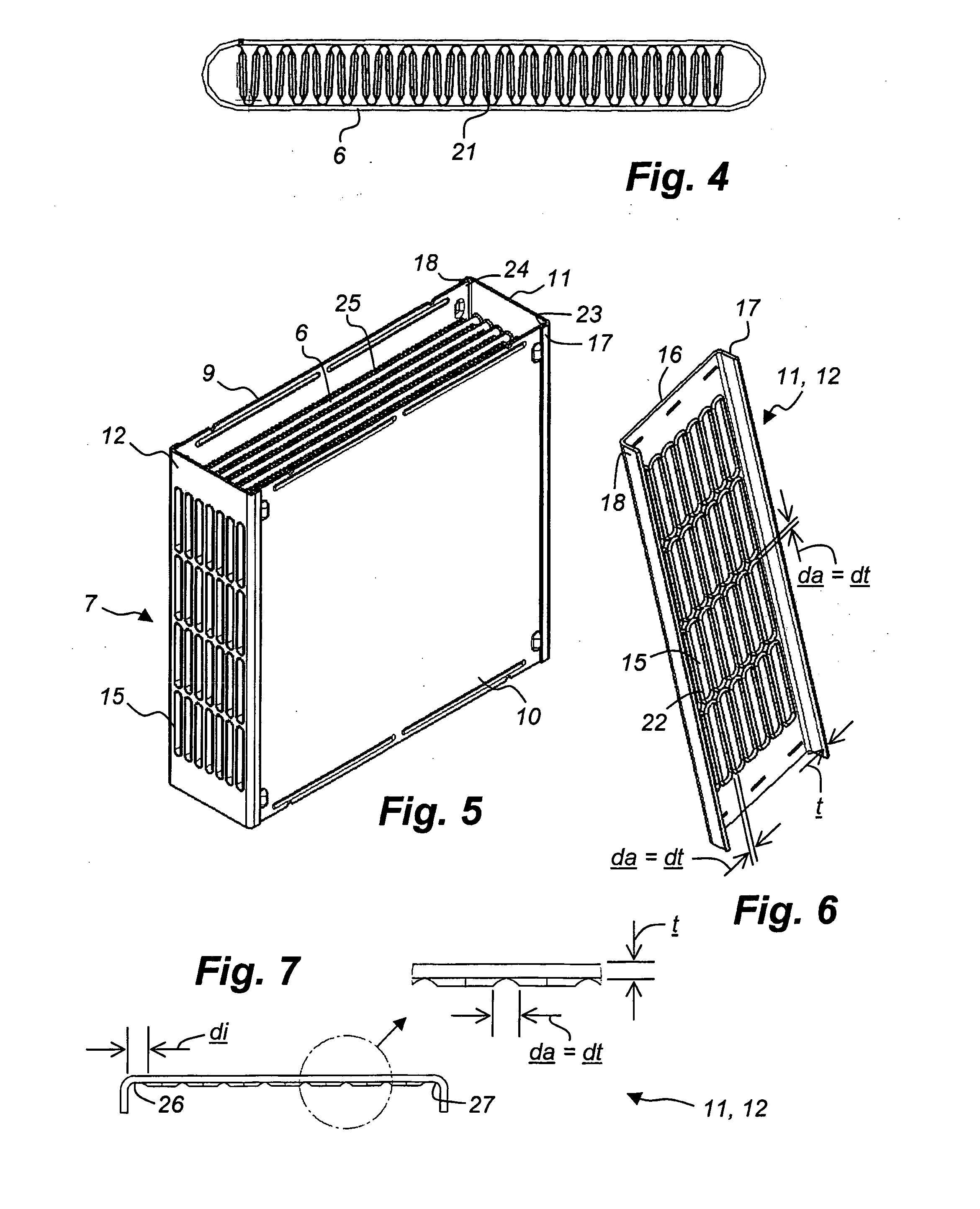
[0024]In WCCACs an important issue is to avoid leakage of coolant into the charged air led to the engine, because otherwise engine failure would be the consequence. Therefore it is of utmost importance to guarantee absolute fluid tightness between the air side and the coolant side of a WCCAC. In the heat exchanger 1 shown in FIG. 1 the air side consists of two air tanks 2, 3 with an air inlet 4 and an air outlet 5, respectively, and of a plurality of air tubes, which are shown in FIGS. 2, 4 and 5 and designated 6. They are described in further detail below. The coolant side of the heat exchanger 1 in FIG. 1 consists of a coolant ...


PUM


Abstract

The invention concerns a header plate, preferably for a heat exchanger, such as water cooled charge air cooler (WCCAC), comprising a coolant housing having two opposing walls made up from two header plates (11, 12), which are made of sheet metal of a defined thickness (t). The header plates (11, 12) form parts of air tanks and are passed by air tubes extending through said coolant housing from one of said header plates (11, 12) to the other. The header plates (11, 12) have stamped apertures (15), in which said air tubes are inserted and tightly connected to the header plate sheet metal. The apertures (15) have peripheral rims (22), which protrude on one side of the header plate (11, 12) in question and give an extra support to the air tubes inserted in the apertures (15) of said header plate (11, 12). The distance (da) between adjacent apertures (15) and thus the distance (dt) between adjacent air tubes is less than two times the thickness (t) of the header plate sheet metal.

Description

TECHNICAL FIELD[0001]The invention concerns a header plate and a heat exchanger comprising same. The header plate as such is made of sheet metal of a defined thickness and has apertures stamped therein for receiving air tubes suitable to be inserted in the header plate. The heat exchanger comprises a coolant housing passed by a plurality of air tubes, which are inserted in and attached to apertures in at least one such header plate.PRIOR ART[0002]A heat exchanger comprising header plates according to the preamble and intended for combustion engines is known from the German patent application DE 103 02 708 A1. In that document the header plates are intended to hold a plurality of flat air tubes, which are arranged in parallel with each other with narrow long sides facing a main coolant flow and wide long sides in a side by side configuration. The ends of each air tube are inserted in and tightly attached to stamped apertures of opposing header plates of an inlet air tank and an outle...

Claims


Application Information

Patent Timeline
IPC IPC(8): F28F9/02
CPCF28D2021/0082F02B29/0462F28F9/182F28F9/04Y02T10/146Y02T10/12
Inventor AMAYA, LUIS
Owner VALEO SYST THERMIQUES
Why Eureka
Try Eureka