
Elastic signal transmission cable

a transmission cable and elastic technology, applied in the direction of cables, insulated conductors, conductors, etc., can solve the problems of not showing elasticity, none of these coaxial cables impart elasticity by winding around an elastic core material, and none of these cables have been imparted with elasticity

Active Publication Date: 2011-04-21
ASAHI KASEI FIBERS CORPORATION
View PDF18 Cites 18 Cited by
  • Summary
  • Abstract
  • Description
  • Claims
  • Application Information

AI Technical Summary

Benefits of technology

[0036]The elastic signal transmission cable of the present invention is useful as a transmission cable for robots or wearable electronic devices since it is able to propagate high-speed signals without causing signal disturbance or attenuation, has elasticity and has shape deformation tracking capability.

Problems solved by technology

However, although both of these cables are resistant to bending, they do not demonstrate elasticity.
On the other hand, although coaxial cables are typically rigid and are known to be imparted with elasticity by forming into a so-called curl cord, none of these coaxial cables impart elasticity by winding around an elastic core material.
In addition, twisted pair cables consist of tightly twisting two conductor wires, and none of these cables have been imparted with elasticity.
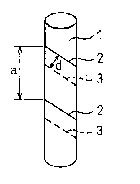
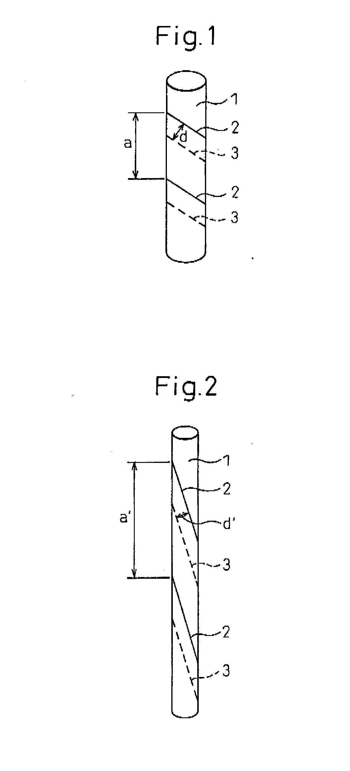
When a conductor wire is wound in one direction around an elastic core material, a large amount of winding torque remains resulting in the occurrence of twisting.
However, since signal transmission cables lack elasticity, the length of wires at the locations of bends (such as the joints of a robot) is required to be equal to or longer than the maximum length during operation.
Consequently, problems occur such as sagging of the cable during operation, cables becoming pinched in or caught on bending portions causing disconnections therein, and cables becoming disconnected from connectors.
In addition, in the case of wearable electronic devices, since the wiring lacks elasticity, these devices require the use of a large jacket and the like, thereby resulting in problems such as being unable to produce wearable electronic devices that closely fit the contour of the body or causing discomfort when worn.

Method used


Image

  • Elastic signal transmission cable
  • Elastic signal transmission cable
  • Elastic signal transmission cable

Examples


examples

[0178]Although the following provides a detailed explanation of the present invention based on examples and comparative examples, the present invention is not limited to only these examples.

[0179]The evaluation methods used in the present invention are as indicated below.

[0180](1) Elasticity

[0181]Marks were made on elastic signal transmission cables at 20 cm intervals. While holding the outside of the cables by hand, the cables were stretched so that the locations of the marks were 22 cm apart, after which the cables were relaxed and measured for length. The cables were categorized according to the following criteria. Cables able to be stretched to 22 cm and subsequently returned to less than 21 cm after relaxing (A) were evaluated as having elasticity of 10% or more.[0182]A: Able to be stretched to 22 cm and returned to less than 21 cm after relaxing[0183]B: Unable to be stretched to 22 cm, or able to be stretched to 22 cm but did not return to less than 21 cm even if relaxed

[0184]...

examples 1 and 2

)

[0236]Using a 940 dtex polyurethane elastic long fiber (Asahi Kasei Fibers Corp., trade name: Roica) as a core, 230 dtex wooly nylon (black-dyed yarn) was wound at a stretch ratio of 4.2 around the core by lower twisting at 700 T / M and upper twisting at 500 T / M to obtain a double cover yarn. The resulting double cover yarn was wound onto braiding bobbins, four of the bobbins were uniformly arranged with two bobbins in the S direction and two bobbins in the Z direction of an 8-cord braiding machine to braid the yarn and obtain an elastic cylindrical body having a diameter of 1.8 mm. This elastic cylindrical body was stretched 2.2 times by a special-purpose braiding machine (braiding machine provided with (1) a mechanism for supplying the elastic cylindrical body as a core, (2) a mechanism for feeding the elastic cylindrical body by grasping by aligning in a FIG. 8 with the V-grooves of a series of two rollers having a plurality of v-grooves, (3) a mechanism for winding up the elasti...

examples 3 and 4

[0238]Using natural rubber No. 18 square rubber (Marueinissan Co., Ltd.) for the core, an outer cover was provided with a 16-cord braiding machine using wooly nylon (230 dtex (black-dyed yarn)×3 ply yarn) while stretching by a factor of 4 times to obtain an elastic cylindrical body having a diameter of 2.5 mm. Elastic signal transmission cables of the present invention were produced in the same manner as Examples 1 and 2 with the exception of using the resulting elastic cylindrical body. The composition and evaluation results of the resulting elastic signal transmission cables are also shown in Table 1.


PUM

PropertyMeasurementUnit
Fractionaaaaaaaaaa
Fractionaaaaaaaaaa
Fractionaaaaaaaaaa

Abstract

An object of the present invention is to provide an elastic signal transmission cable having a length of several centimeters to several meters that has a shape deformation tracking ability and enables high-speed signal transmission. The inventive elastic signal transmission cable has an elasticity of 10% or more and transmission loss of 10 dB / m or less in a relaxed state at 250 MHz, and comprises an elastic cylindrical body having an elasticity of 10% or more and a conductor portion containing at least two conductor wires wound in the same direction around the elastic cylindrical body.

Description

TECHNICAL FIELD[0001]The present invention relates to an elastic signal transmission cable having elasticity and superior high-speed signal transmission properties.BACKGROUND ART[0002]Signal transmission cables mainly consist of coaxial cables, twisted pair cables and flexible flat cables. Known examples of cables having superior flexibility and bendability include a flexible flat cable that uses a polyolefin resin for a lowly conductive layer (see Patent Document 1), and a flexible flat cable in which a flexible printed circuit board is wound in the form of a spiral around a core material (see Patent Document 2). However, although both of these cables are resistant to bending, they do not demonstrate elasticity.[0003]In the case of designing a high-speed signal transmission cable, the distance between two conductor wires and the dielectric surrounding the conductor wires are known to affect transmission properties. Consequently, it is a common practice to maintain a constant distan...

Claims


Application Information

Patent Timeline
IPC IPC(8): H01B7/06H01R43/00
CPCH01B7/06Y10T29/49117H01B11/00H01B7/04H01B11/18H01B11/02H01B11/12H01B13/008H01B17/36
Inventor TATSUMI, SHUNJIYUUKI, YASUNORIMAKINO, HIROYUKI
Owner ASAHI KASEI FIBERS CORPORATION
Learn More