Spill containment system

a technology of containment system and spray tube, which is applied in the direction of transportation and packaging, manufacturing tools, liquid transfer devices, etc., can solve the problems of ground water contamination, drop tube itself and/or any number of other devices that may require periodic inspection, and may cause environmental problems

Active Publication Date: 2011-04-21
FRANKLIN FUELING SYST
View PDF13 Cites 10 Cited by
  • Summary
  • Abstract
  • Description
  • Claims
  • Application Information

AI Technical Summary

Benefits of technology

[0015]In still another embodiment thereof, the present invention provides a method of using a fluid spill collector assembly, comprising: removing a cover from a cover receiving surface to expose an inner cavity of a spill receptacle; retrieving a drain valve actuator from within the inner cavity; attaching the drai

Problems solved by technology

In addition to wasted liquid material, the hazardous chemicals may leach into the soil causing environmental problems, such as ground water contamination.
Moreover, the drop tube itself and/or an

Method used


Image

  • Spill containment system
  • Spill containment system
  • Spill containment system

Examples


Embodiment Construction

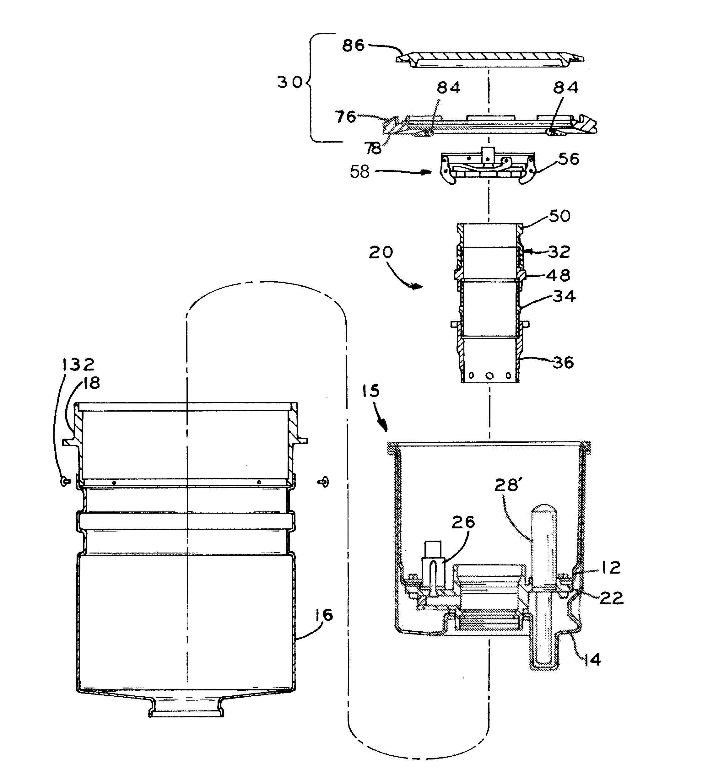
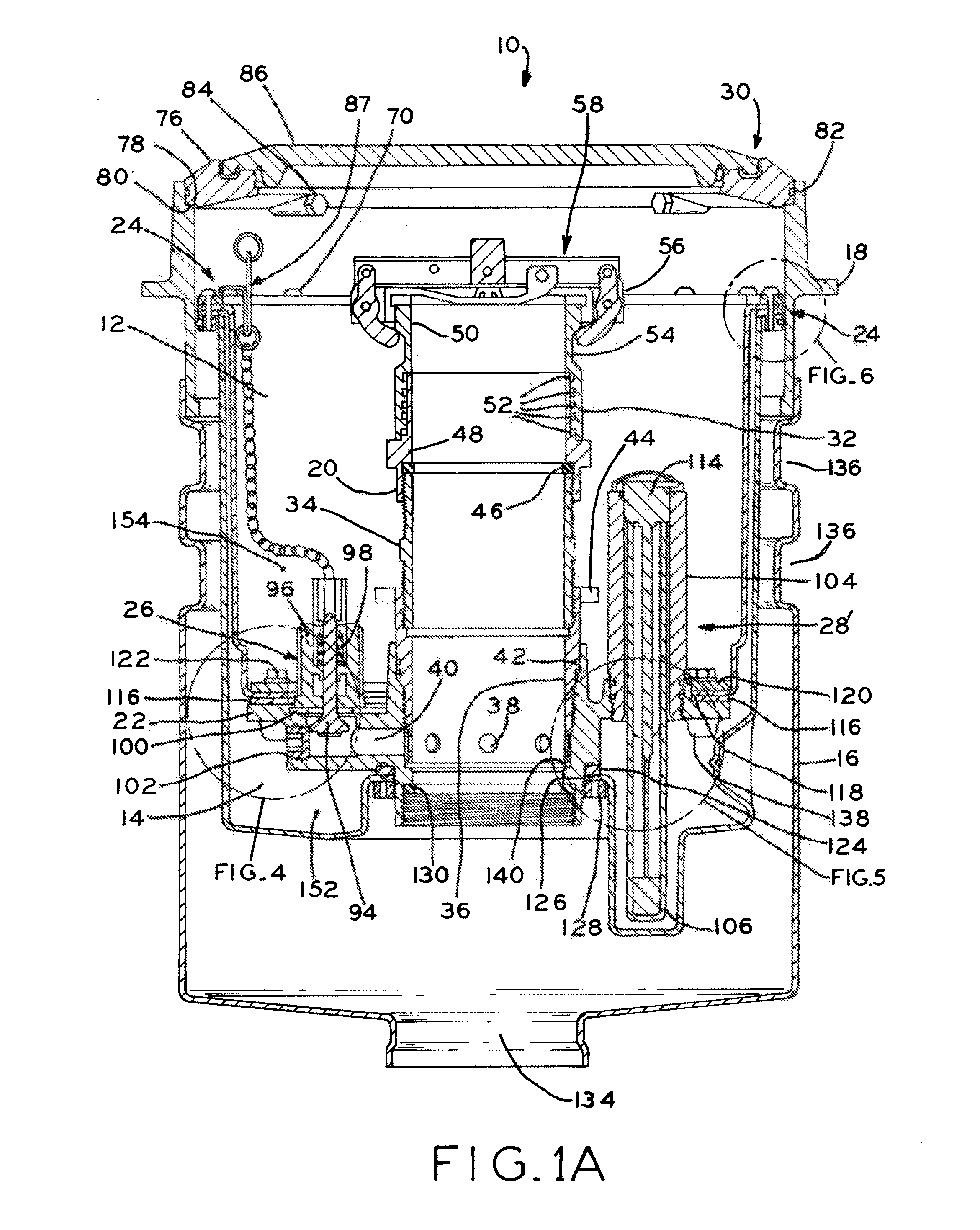
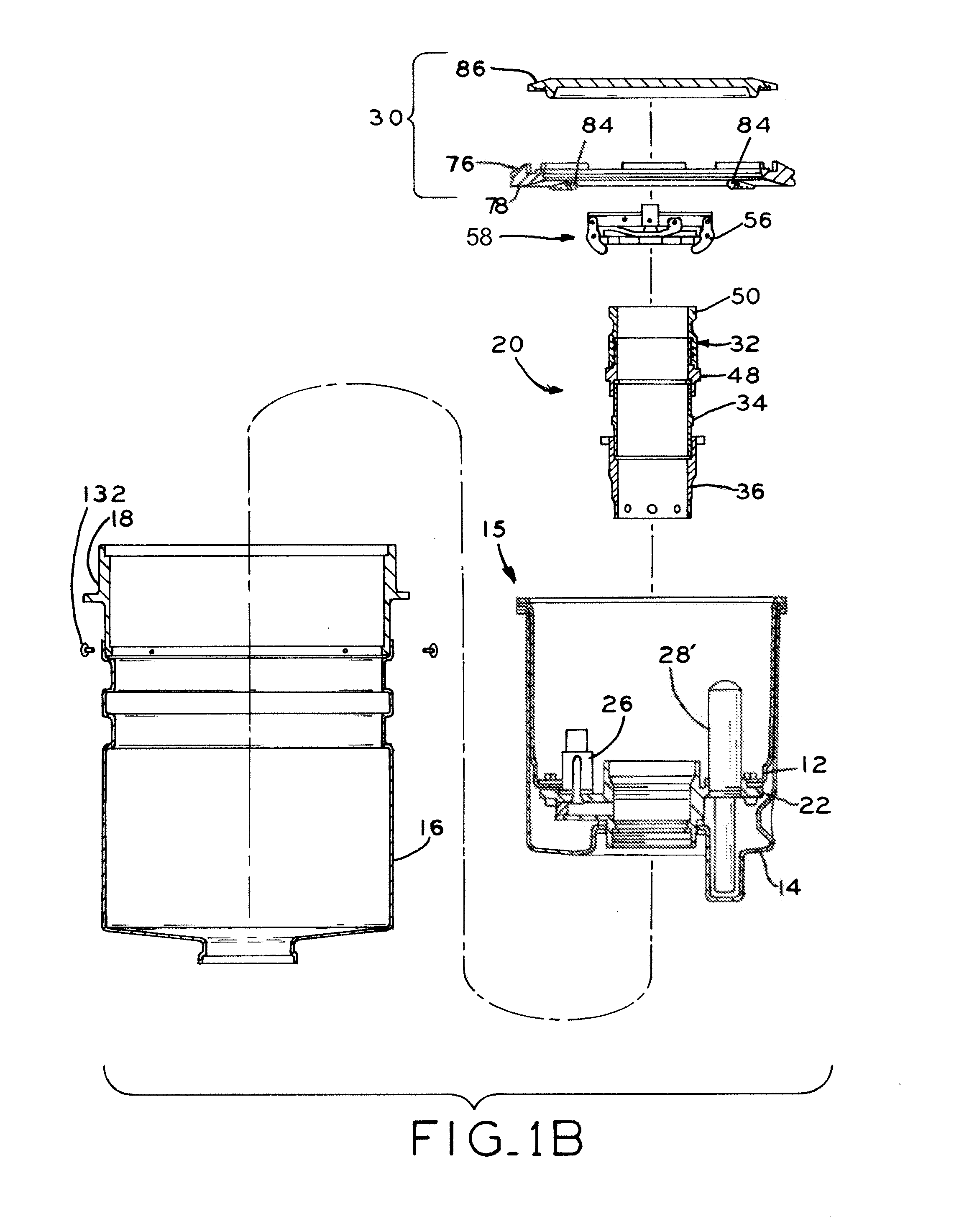
[0035]Referring generally to FIGS. 1A and 1B, a spill collection system 10 includes a primary, inner spill receptacle 12 received within a secondary, outer spill receptacle 14, which in turn is at least partially received by gravel guard or exterior wall 16 at a lower end and concrete ring or collar 18 at an upper end. In the illustrated embodiment, exterior wall 16 and collar 18 are considered to be stationary, in that they are permanently or semi-permanently installed at a subterranean storage tank access point. Primary spill receptacle 12 has a generally cylindrical wall with openings formed at the upper and lower ends thereof, while secondary spill receptacle 14 has a larger (i.e., increased diameter) cylindrical wall also having openings formed at the upper and lower ends of thereof. As discussed below, primary spill receptacle 12 is “nested” within secondary spill receptacle 14, so that the upper opening of receptacle 12 remains open while the upper opening of receptacle 14 is...


PUM

PropertyMeasurementUnit
Pressureaaaaaaaaaa
Interstitialaaaaaaaaaa

Abstract

A spill containment system is attachable to a riser pipe with an axially moveable seal. The spill containment system allows access to a drop tube in the riser pipe via a removable liquid communication assembly. The spill containment system includes a sealed interstitial space, which remains sealed during installation, service and use of the system. The spill containment system is protected by a weather resistant cover assembly.

Description

CROSS-REFERENCE TO RELATED APPLICATIONS[0001]This application claims the benefit under Title 35, U.S.C. §119(e) of U.S. Provisional Patent Application Ser. No. 61 / 252,311, entitled SPILL CONTAINMENT SYSTEM, filed Oct. 16, 2009, the disclosure of which is expressly incorporated by reference herein in its entirety.BACKGROUND[0002]1. Technical Field[0003]The present disclosure relates to a spill containment system for use with a fill pipe. More particularly, the present relation relates to a spill containment system for use in conjunction with a riser pipe of an underground storage container, such as an underground fuel storage tank, and to a method for using the same.[0004]2. Brief Description of the Related Art[0005]Liquid storage tanks are used for storage and distribution of a variety of liquids, such as reactants, solvents, chemical byproducts and finished materials. Underground liquid storage tanks for storing fuel are in wide spread use at gasoline service stations and fuel stor...

Claims


Application Information

Patent Timeline
IPC IPC(8): B65D21/00B65D45/00B23P19/00B65D90/503B65D90/511
CPCB67D7/3209B65D90/24Y10T29/49815B65D90/503B65D90/105Y10T29/49817Y10T137/5762B65D90/511
Inventor KUEHN, JUSTIN F.
Owner FRANKLIN FUELING SYST
Why Eureka
Try Eureka