Composite rim and a wheel having such rim

a composite material and rim technology, applied in the direction of spoked wheels, non-metallic wheel bodies, transportation and packaging, etc., can solve the problems of not being able the problem of polymerization raising serious problems with respect to the adhesive hold, and the inability to assemble the composite material surface by adhesive onto a metallic profile element, etc., to improve the braking quality, and optimize the weight of metallic profil

Inactive Publication Date: 2011-04-21
MAVIC SA
View PDF8 Cites 22 Cited by
  • Summary
  • Abstract
  • Description
  • Claims
  • Application Information

AI Technical Summary

Benefits of technology

[0019]The invention also provides a rim combining a metallic profile element and a composite covering, in which braking, i.e., the contact of the brake pads with the rim, is carried out on the covering which has improved stability over time.
[0027]Furthermore, the composite material that rises along the sidewalls of the metallic profile element contributes to the mechanical strength of the profile element and in particular makes it possible to increase its strength and that of the attachment zones with respect to the stresses incurred during tire inflation, in the case of a rim for clincher tires. This makes it possible to optimize the weight of the metallic profile element and, therefore, that of the rim as a whole. Furthermore, the configuration of the profile element defines a predetermined configuration of the rim in the braking zone, and it has been surprisingly determined that this configuration makes it possible to improve the braking quality substantially, compared to known rims that are entirely composite.

Problems solved by technology

The covering is fixed, for example, by adhesive on the sidewalls of the metallic profile element, over a portion of the height thereof, the top of the profile element remaining uncovered to provide metallic braking surfaces adapted to cooperate with the brakes of the bicycle, braking on composite material surfaces being widely known to be less effective.
Furthermore, because the covering is premade in a single piece and is non-deformable, it would not be possible to assemble it by adhesive onto a metallic profile element that is also non-deformable.
This solution involving adhesive by polymerization raises serious problems with respect to the adhesive hold over time, especially for this particular type of rim.
The thermal energy generated during braking, over time, damages the bond between the metallic profile element and the composite covering.
It is also known to have rims made entirely out of carbon; these rims are generally not adapted for use with nontubular tires (i.e., clincher tires) because it is difficult, with composite material, to obtain profile elements with connection zones having isotropic strength for fastening the tires.

Method used


Image

  • Composite rim and a wheel having such rim
  • Composite rim and a wheel having such rim
  • Composite rim and a wheel having such rim

Examples


Embodiment Construction

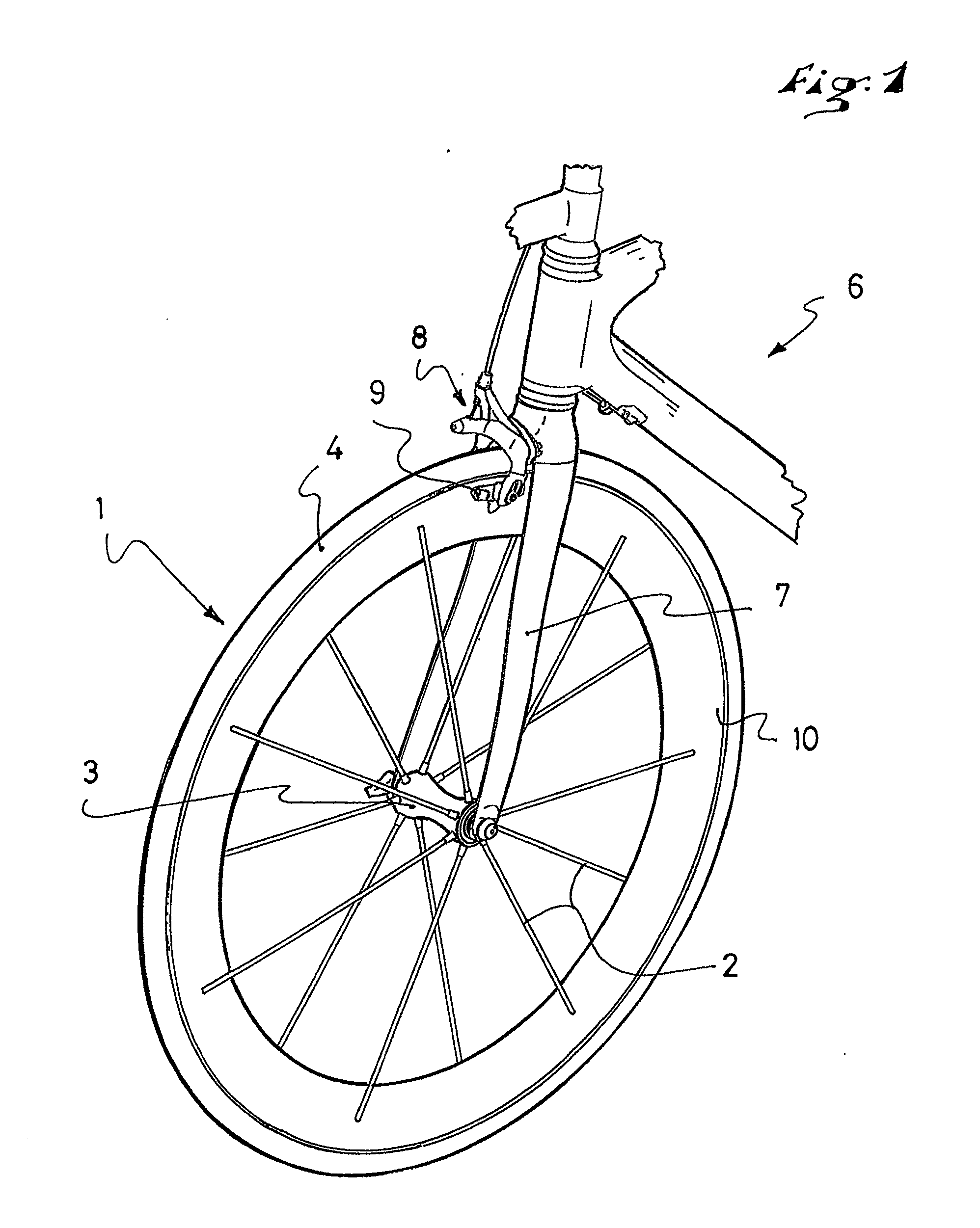
[0033]FIG. 1 is a partial view, in perspective, of a cycle, i.e., a bicycle, equipped with a wheel according to the invention. The bicycle 6 includes, among other things, a front fork 7 between the blades of which a wheel 1 is mounted. In a known configuration, the wheel 1 includes a peripheral rim 10 and a central hub 3. A plurality of spokes 2 are arranged between the hub 3 and the rim.

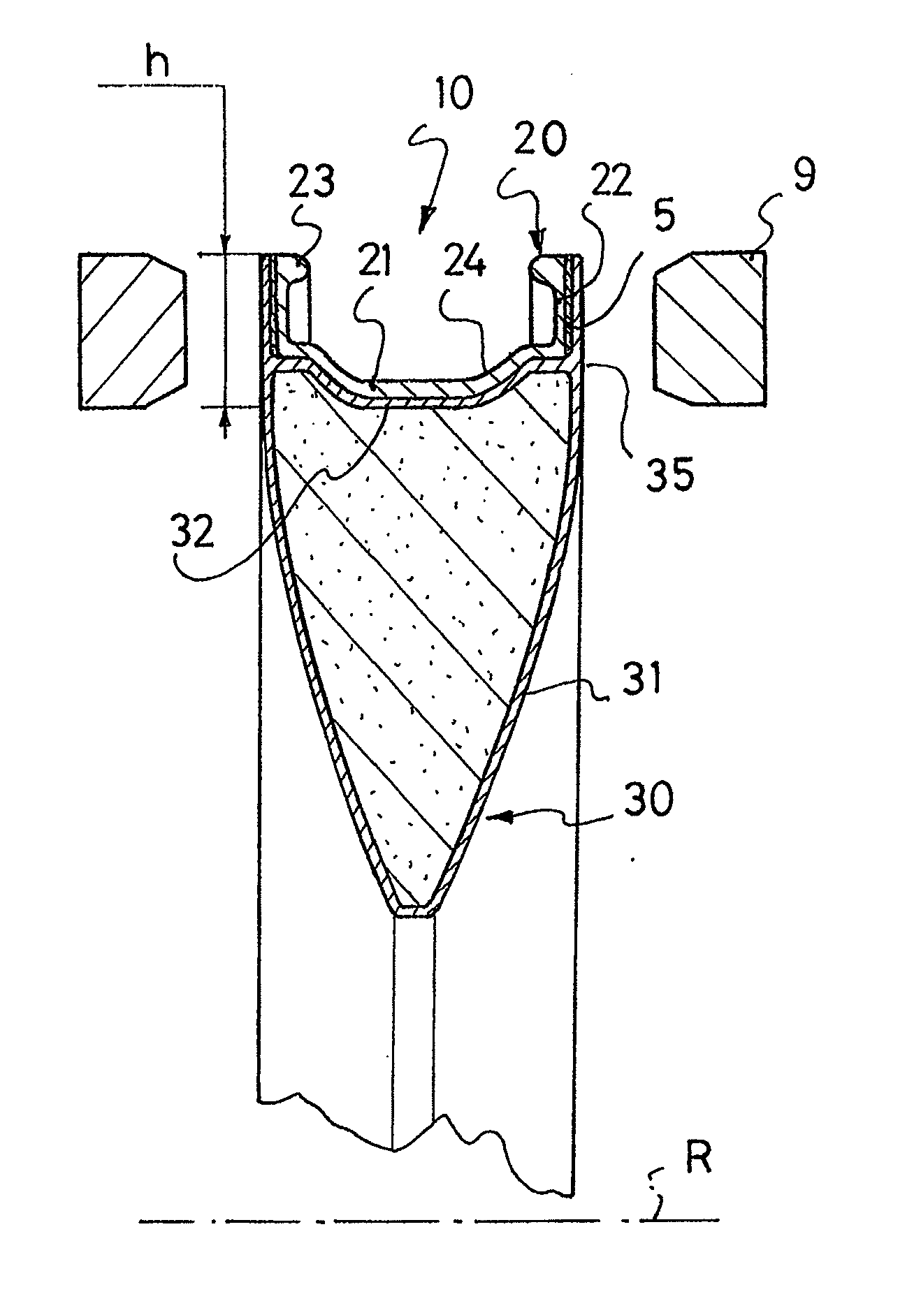
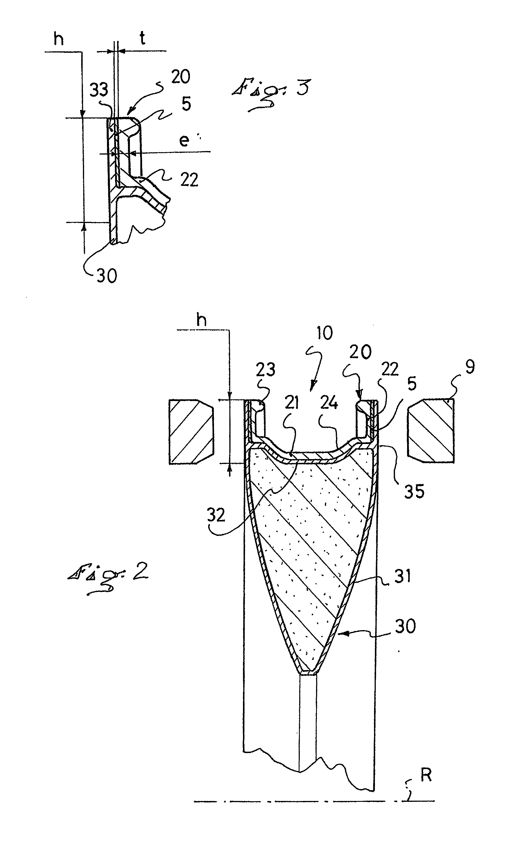
[0034]The bicycle 6 also includes a braking device which distributes the braking force on the front wheel 1 and the rear wheel (not shown). The front brake 8 functions by application of two pads 9 against the rim 10. Each of the two pads is mounted at the end of a pivoting stirrup. An actuation by cable, controlled from the handlebar by means of a lever, causes the stirrups to pivot so as to press the pads 9 against the rim 10. The portions of the side surfaces of the rim against which the pads are applied are called the braking surfaces, or flanks, 33. The braking flanks constitute the outer side s...


PUM

PropertyMeasurementUnit
heightaaaaaaaaaa
heightaaaaaaaaaa
heightaaaaaaaaaa

Abstract

A cycle rim that includes a metallic profile element, a covering made of composite material and including fibers embedded in a first matrix that covers the metallic profile element, at least over a portion thereof, and further including a spacer which is inserted between the profile element and the covering. The metallic profile element includes at least two sidewalls connected by a bridge, the covering including at least two flanks, each of the flanks covering one of the sidewalls, and the spacer is inserted between each of the sidewalls and the flank which covers it.

Description

CROSS-REFERENCE TO RELATED APPLICATION[0001]This application claims priority under 35 U.S.C. §119 of French Patent Application No. 09 04951, filed on Oct. 15, 2009, the disclosure of which is hereby incorporated by reference thereto in its entirety.BACKGROUND OF THE INVENTION[0002]1. Field of the Invention[0003]The invention relates to a rim for a spoked wheel, in particular a rim for a spoked wheel of a bicycle. The invention also relates to a wheel including such a rim.[0004]2. Background and Other Information[0005]In a known fashion, a bicycle rim has an at least partially box-shaped annular profile element, i.e., such as an annular element having a constant cross-sectional shape, which includes one or two bridges, i.e., a lower bridge and an upper bridge, respectively; as well as two sidewalls connected by the bridge(s), the sidewalls extending radially outwardly to form a pair of transversely opposed flanges, the flanges forming, with the upper bridge, a channel for receiving t...

Claims


Application Information

Patent Timeline
Patent Type & Authority Applications(United States)
IPC IPC(8): B60B5/02B60B1/02
CPCB60B5/02B60B21/025B60B21/08B60B21/104B60Y2200/134B60B2360/341B60B2360/344B60B2360/36B60B2360/368B60B2310/241
Inventor SAILLET, BENOIT
Owner MAVIC SA
Why Eureka
Try Eureka