
Light-emitting element lamp and lighting equipment

a technology of light-emitting elements and lamps, which is applied in the direction of discharge tubes/lamp details, lighting support devices, gas-filled discharge tubes, etc., can solve the problems of adversely affecting the service life and lowering the optical output, and achieves improved thermal conduction, simple structure, and effective radiation of heat

Inactive Publication Date: 2011-04-21
TOSHIBA LIGHTING & TECH CORP
View PDF93 Cites 22 Cited by
  • Summary
  • Abstract
  • Description
  • Claims
  • Application Information

AI Technical Summary

Benefits of technology

[0011]According to Claim 1 of the present invention, a temperature rise of the substrate having light-emitting elements mounted thereon can be effectively prevented by using the thermally conductive casing and the thermally conductive cover. Further, since the thermally conductive casing is widened toward the irradiation opening, and the area of the outer circumferential surface which brings about a heat radiation effect is large, the casing is effective in the heat radiation effect. Furthermore, since the thermally conductive casing and the thermally conductive cover are brought into surface contact with each other, the thermal conduction is improved.
[0012]According to Claim 2 of the present invention, a waterproof feature is maintained with a simple structure, and a power feeding channel to the light source part can be secured, in addition to the effects of the present invention, which are described in Claim 1 of the present invention.
[0013]According to Claim 3 of the present invention, in addition to the effects of Claim 1 or 2 of the present invention, light distribution control is enabled by the reflection surface of the reflector per light-emitting element, wherein desired optical treatment can be carried out without any other light control means provided.
[0014]According to Claim 4 of the invention, in addition to the effects which are brought about by the light-emitting element lamp, it is possible to provide lighting equipment capable of effectively radiating heat by transmitting heat from the cap to the socket.

Problems solved by technology

In regard to the light-emitting element such as an LED, an increase in temperature thereof results in a lowering in optical output and adversely influences the service life.

Method used


Image

  • Light-emitting element lamp and lighting equipment
  • Light-emitting element lamp and lighting equipment
  • Light-emitting element lamp and lighting equipment

Examples


Embodiment Construction

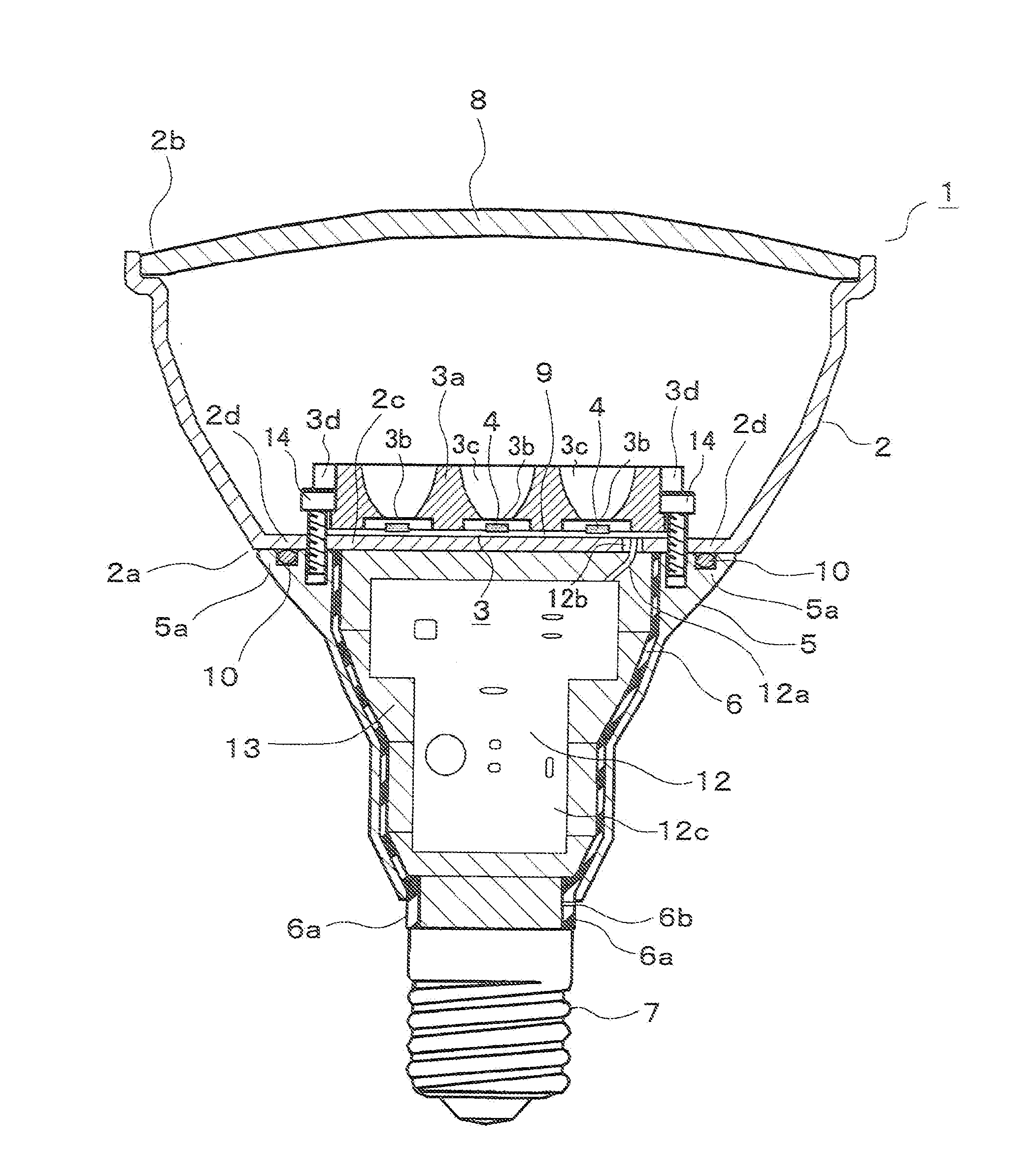
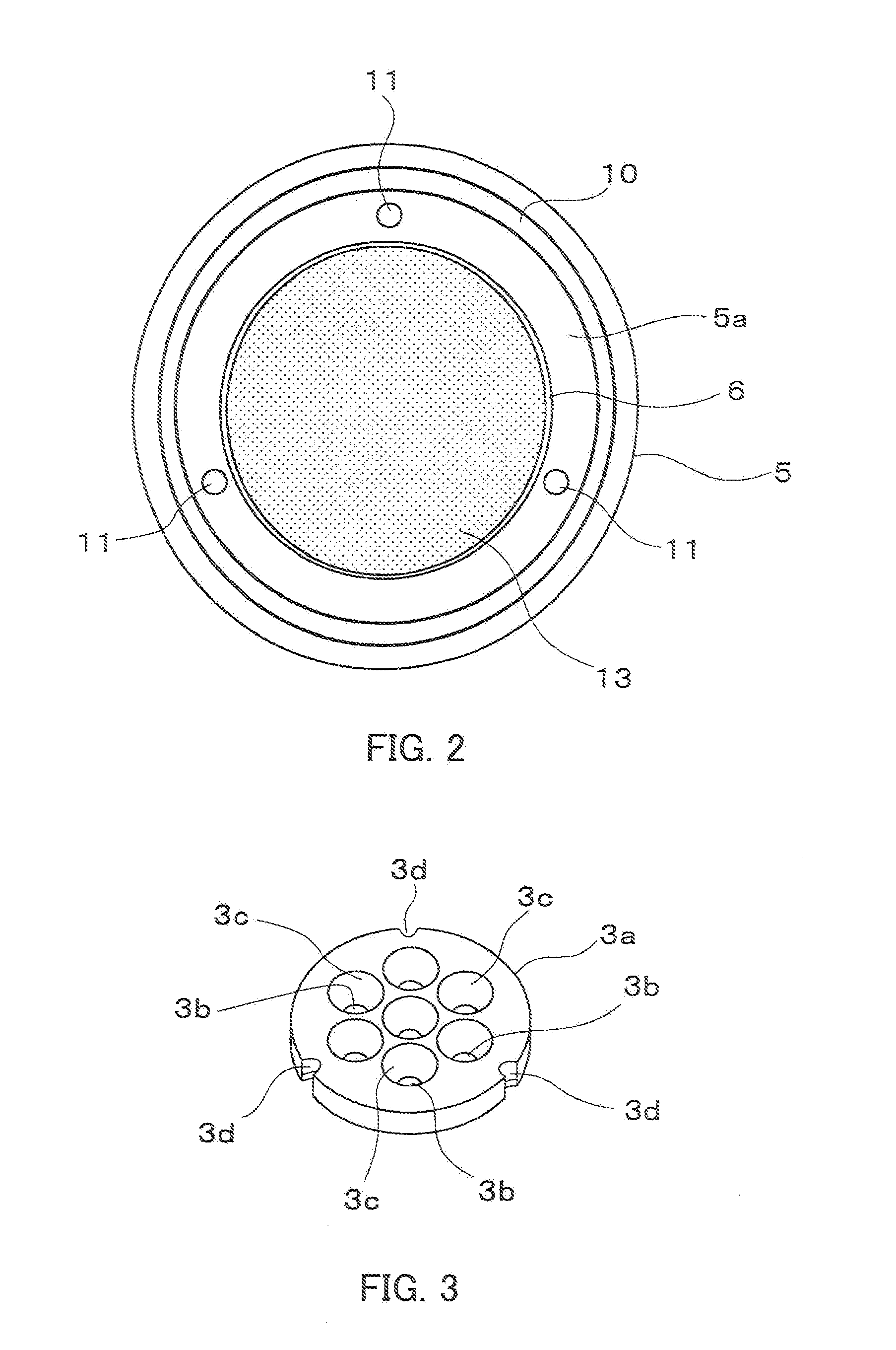
[0020]Hereinafter, a description is given of a light-emitting element lamp according to the embodiment of the present invention with reference to FIG. 1 through FIG. 4. FIG. 1 is a sectional view showing the light-emitting element lamp, FIG. 2 is a plan view showing the same light-emitting element lamp with the thermally conductive casing removed, FIG. 3 is a perspective view showing a reflector of the same light-emitting element lamp, and FIG. 4 is a sectional view showing a reflector of the same light-emitting element lamp. The light-emitting element lamp according to the present embodiment can replace the existing reflection type incandescent lamp or a so called beam lamp and has a structure roughly equivalent to the beam lamp in respect to the appearance dimension. The beam lamp is suitable as a store spot light, projection illumination of buildings and advertisement sign boards, and illumination of construction sites, etc.

[0021]In FIG. 1, the light-emitting element lamp 1 has a...


PUM


Abstract

The present invention provides a light-emitting element lamp 1 capable of preventing a temperature rise of a substrate 9, on which light-emitting elements 4 are mounted, by effectively utilizing a thermally conductive casing 2 and a thermally conductive cover 5. The light emitting element lamp 1 includes a thermally conductive casing 2, a light source part 3, a thermally conductive cover 5, and an insulative cover 6. The thermally conductive casing 2 includes an irradiation opening 2b, is formed so as to be widened toward the irradiation opening 2b, has its outer circumferential surface exposed outwardly, and has a substrate mounting part 2c secured on its inner circumferential surface. The light source part 3 has a substrate 9 having the light-emitting elements 4 mounted thereon and causes the substrate 9 to be thermally coupled to and attached to the substrate mounting part 2c of the thermally conductive casing 2. The thermally conductive cover 5 is thermally coupled to and connected to the outer circumferential surface of the thermally conductive casing 2 in a surface-contacted state. The insulative cover 6 has one end side thereof connected to the thermally conductive cover 5, and the cap 7 is connected to the other end side thereof. The lighting circuit 12 controls lighting of the light-emitting elements 4 accommodated in the insulative cover 6.

Description

TECHNICAL FIELD[0001]The present invention relates to a light-emitting element lamp to which light-emitting elements such as LEDs are applied as a light source, and lighting equipment using the light-emitting element lamp.BACKGROUND ART[0002]In regard to the light-emitting element such as an LED, an increase in temperature thereof results in a lowering in optical output and adversely influences the service life. Therefore, in a lamp in which a solid-state light-emitting element such as an LED and EL element are used as its light source, it is necessary to prevent the temperature of the light-emitting element from rising in order to improve various characteristics such as service life and efficiency. Conventionally, in this type of LED lamp, such a type of LED lamp has been known which is provided with a columnar radiator between a substrate having LEDs disposed thereon and a cap and the substrate is attached to the peripheral edge at the end face of the radiator (For example, refer ...

Claims


Application Information

Patent Timeline
Patent Type & Authority Applications(United States)
IPC IPC(8): H01J61/52F21S2/00F21Y101/02H01L33/60H01L33/64
CPCF21K9/1375F21V29/87F21V21/30F21Y2101/02H01L25/0753H01L33/60H05B33/0803Y02B20/383F21V31/04F21V31/005F21V17/12F21V23/001F21V23/006H01L2924/0002F21V7/0083H01L2924/00F21K9/23F21Y2115/10F21K9/238Y02B20/30F21K9/68H05B45/30H05B45/3574
Inventor SUWA, TAKUMITANAKA, TOSHIYAHISAYASU, TAKESHIOSAWA, SHIGERU
Owner TOSHIBA LIGHTING & TECH CORP
Features
  • Generate Ideas
  • Intellectual Property
  • Life Sciences
  • Materials
  • Tech Scout
  • Unparalleled Data Quality
  • Higher Quality Content
  • 60% Fewer Hallucinations
Learn More