Screen and projection system

a projection system and screen technology, applied in the field of screens and projection systems, can solve the problems of deteriorating image quality, difficult to display a clear image, and disrupting the white balance of the projection image, so as to maintain image quality, maintain white balance, and low power

Active Publication Date: 2011-04-21
SEIKO EPSON CORP
View PDF10 Cites 1 Cited by
  • Summary
  • Abstract
  • Description
  • Claims
  • Application Information

AI Technical Summary

Benefits of technology

[0031]According to this configuration, a uniform, bright projection image can be obtained even when a low-output projector PJ is used in a bright room, and, because the image can be displayed with the maintained white balance, a projection system PS can be realized that can operate at low power while maintaining image quality.

Problems solved by technology

However, there is a problem in these types of screens.
Accordingly, the contrast, or the luminance ratio between white (maximum luminance) and black (minimum luminance) becomes low in a bright environment, and it is difficult to display a clear image.
The coloring that occurs on the screen in this manner disrupts the white balance of the projection image, and deteriorates image quality.
Such coloring can be a cause of image deterioration in the projection image.
However, changes which may be caused by the reaction of the second pigment only with the room light in the absence of sunlight are limited, and the coloring problem is unlikely to occur, because the quantity of the emitted ultraviolet light is much smaller than the ultraviolet light quantity in sunlight.

Method used


Image

  • Screen and projection system
  • Screen and projection system
  • Screen and projection system

Examples


first embodiment

[0038]A screen and a projection system according to First Embodiment of the invention are described below with reference to FIG. 1 to FIG. 4. Note that, for simplicity, the dimensions of the constituting elements in the drawings are not in scale.

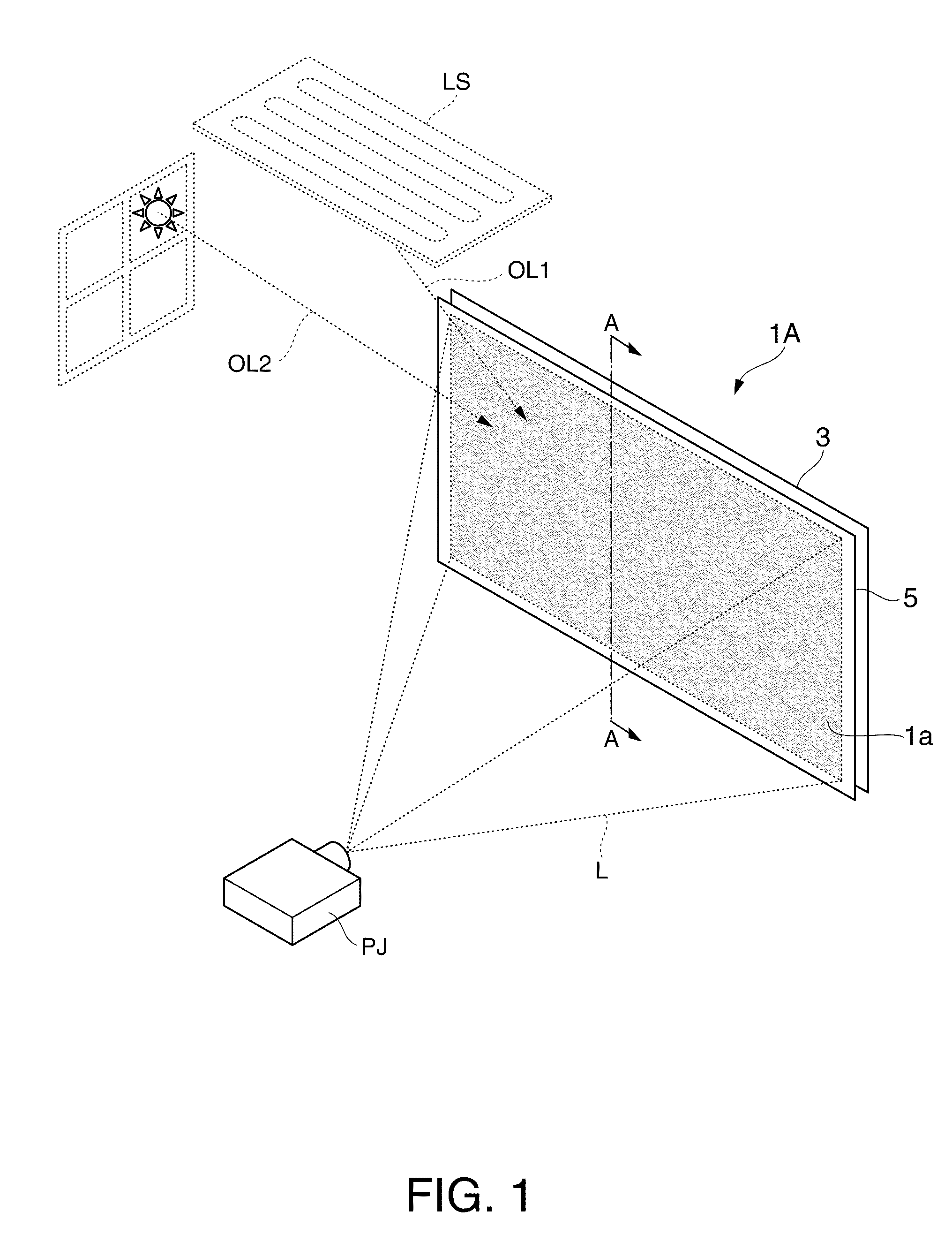
[0039]FIG. 1 is a perspective view illustrating a screen 1A and a projection system PS of the present embodiment.

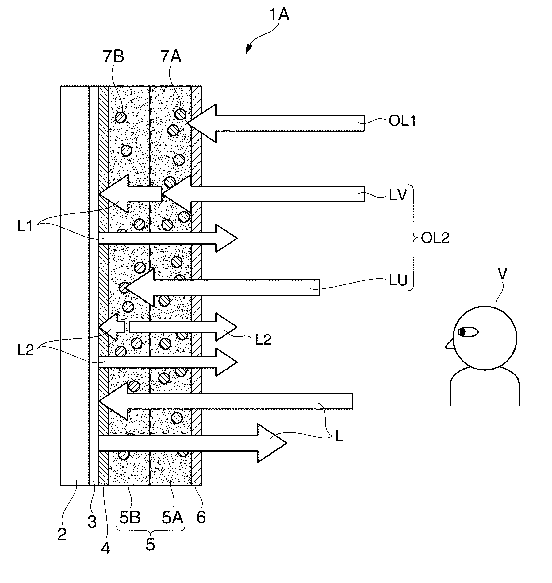
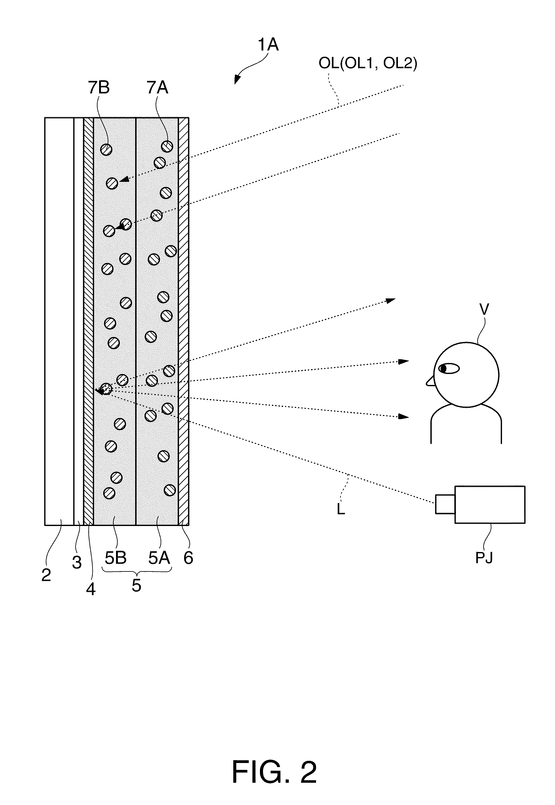
[0040]As illustrated in the figure, the screen 1A of the present embodiment is of a reflection-type, and includes a projection surface 1a; a pigmented layer 5 formed on the projection surface 1a, and that includes pigments that absorb outside light OL1 and OL2; and a reflecting layer 3 provided on the back side of the pigmented layer 5 (opposite from the viewing side). The outside light OL1 is light that originates from a room illumination LS. The outside light OL2 is sunlight.

[0041]The screen 1A has a horizontally long, rectangular planar shape, and reflects back the projected light L from a projector PJ. The projector PJ is a pr...

second embodiment

[0080]FIG. 5 is an explanatory diagram of a screen 1B according to Second Embodiment of the invention. The screen 1B of the present embodiment is partly in common with the screen 1A of the First Embodiment. The difference lies in the properties of the second pigment. Accordingly, the constituting elements common to those described in First Embodiment are given the same reference numerals, and explanations thereof are omitted.

[0081]The explanatory diagram of the screen 1B shown in FIG. 5 corresponds to FIG. 4 of First Embodiment. The second pigment 7C in the second pigmented layer 5B of the screen 1B absorbs the ultraviolet light contained in the outside light OL2 originating from sunlight, and undergoes a change in molecular structure so as to have an absorption band in the visible light region.

[0082]For example, photochromic substances, for example, such as a spiro-oxazine compound can be used as the second pigment 7C. The second pigment 7C is set so that, upon absorbing the ultrav...


PUM


Abstract

A screen includes: a base material; and a pigmented layer provided on one surface of the base material, the pigmented layer including a first pigment that absorbs a visible light component contained in room light, and a second pigment that absorbs ultraviolet light, wherein the second pigment absorbs the ultraviolet light contained in sunlight, and varies the color imparted by a remaining visible light component unabsorbed by the first pigment absorbing the visible light component of the sunlight, the color being varied in such a manner as to reduce the absolute value of a color difference on a chromaticity diagram between a white point and a point indicative of the color imparted by the remaining component.

Description

BACKGROUND[0001]1. Technical Field[0002]The present invention relates to screens and projection systems.[0003]2. Related Art[0004]Various types of screens are available as projection screens used with projectors (projection-type display apparatuses) to display large images in presentations such as in exhibitions and conferences, including academic conference, or in screening of videos such as in home theaters.[0005]However, there is a problem in these types of screens. For example, in a reflection-type screen, the ambient outside light such as illumination light and window sunlight is also reflected in reflecting the projected light from a projector to display a projection image. Accordingly, the contrast, or the luminance ratio between white (maximum luminance) and black (minimum luminance) becomes low in a bright environment, and it is difficult to display a clear image.[0006]In an effort to develop a screen that can achieve high contrast even under bright settings, there have bee...

Claims


Application Information

Patent Timeline
Patent Type & Authority Applications(United States)
IPC IPC(8): G03B21/56G03B21/60G02B5/22
CPCG03B27/56
Inventor OKAMOTO, JUNICHI
Owner SEIKO EPSON CORP
Why Eureka
Try Eureka