Eureka AIR delivers breakthrough ideas for toughest innovation challenges, trusted by R&D personnel around the world.

Light guide plates and backlight module

Active Publication Date: 2011-04-21
TSINGHUA UNIV +1
View PDF2 Cites 59 Cited by
  • Summary
  • Abstract
  • Description
  • Claims
  • Application Information

AI Technical Summary

Benefits of technology

[0006]Direct-type backlight modules, according to the prior art usually include a point light source such as light emitting diode (LED), a reflective plate, and a light guide plate. The light guide plate has a bottom surface and a top surface opposite to the bottom surface. The point light source is located adjacent to the bottom surface. The reflective plate is located on the side of the bottom surface. The light radiated from the point light source enters the light guide plate and hit the top surface with different incident angles. The first part of the lights leave the light guide plate through a refraction of the top surface, and the second part of the light enter the light guide plate through a reflection of the top surface. The second part of the light will leave the light guide plate after refraction between the top surface and the reflective plate. However, an illumination of the light guide plate is not uniform because the illumination of a center part of the top surface opposite to the point light source is more extreme.

Problems solved by technology

However, liquid crystal displays are not self-luminescent, therefore, backlight modules are typically required.
However, an illumination of the light guide plate is not uniform because the illumination of a center part of the top surface opposite to the point light source is more extreme.

Method used


Image

  • Light guide plates and backlight module
  • Light guide plates and backlight module
  • Light guide plates and backlight module

Examples


Embodiment Construction

[0016]The disclosure is illustrated by way of example and not by way of limitation in the figures of the accompanying drawings in which like references indicate similar elements. It should be noted that references to “an” or “one” embodiment in this disclosure are not necessarily to the same embodiment, and such references mean at least one.

[0017]References will now be made to the drawings to describe, in detail, various embodiments of the present light guide plate and direct-type backlight module.

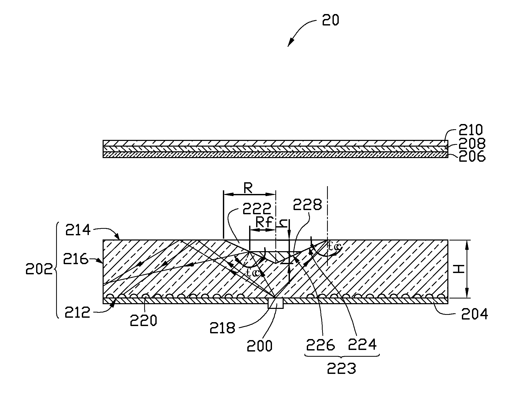
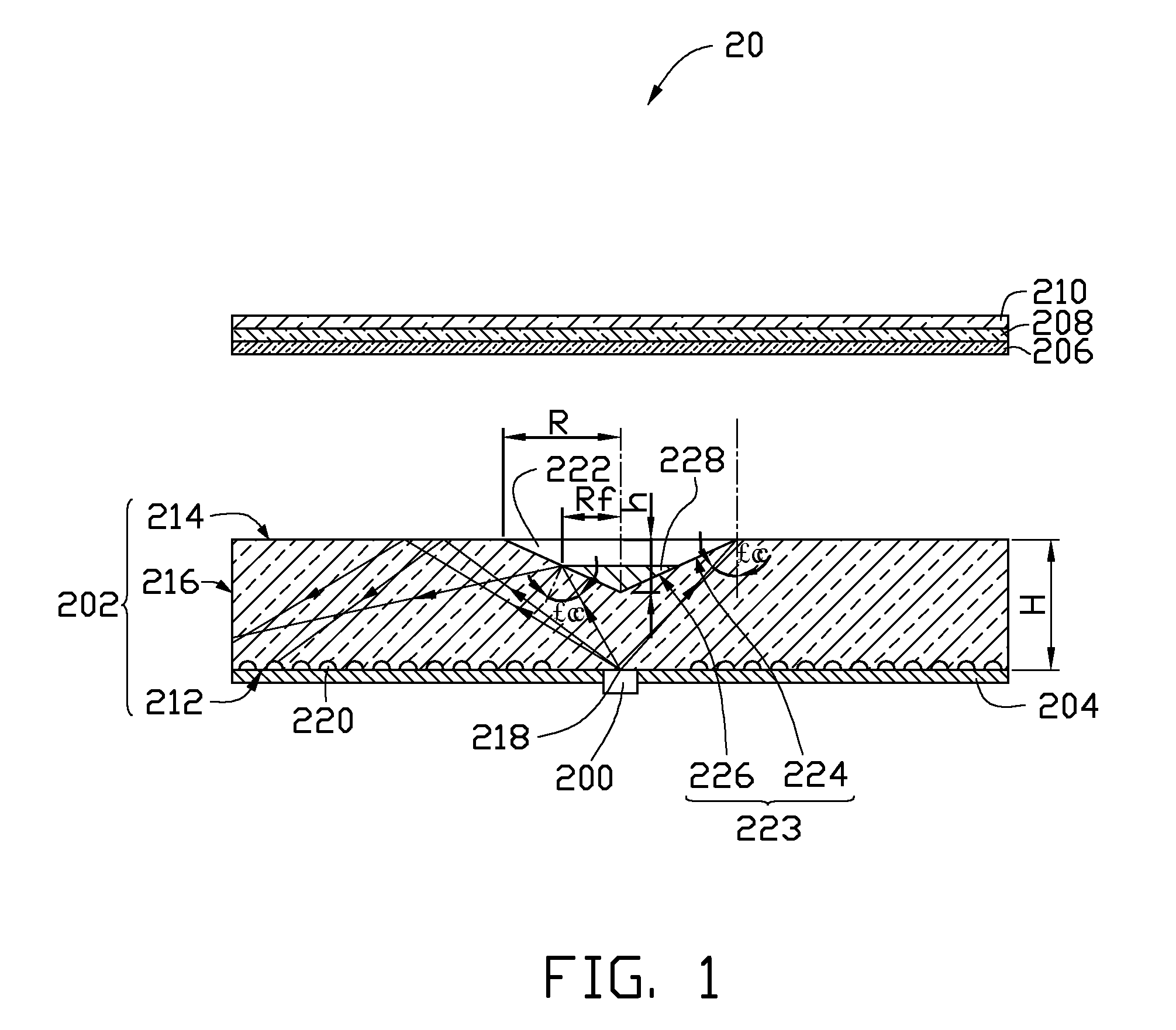
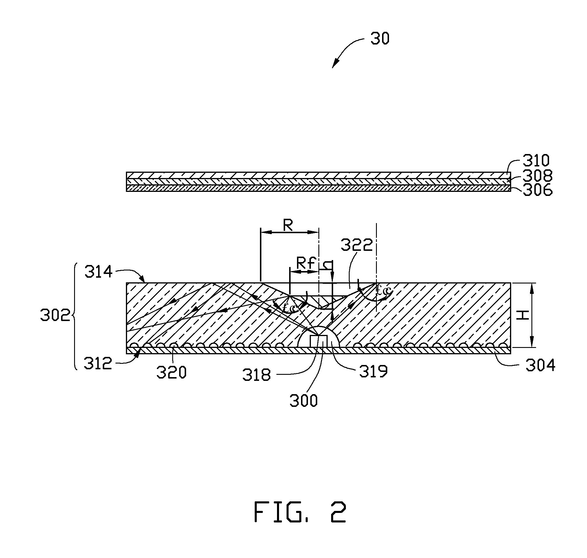
[0018]Referring to FIG. 1, a direct-type backlight module 20 of one embodiment includes a light source 200, a light guide plate 202, a reflective plate 204, a microprism plate 206, a polarization plate 208 and a diffusing plate 210. The light guide plate 202 has a bottom surface 212, a top surface 214 opposite to the bottom surface 212, and at least one lateral side 216. The light source 200 is located adjacent to the bottom surface 212 and aligned with a center 218 of the bottom surface 2...


PUM


Abstract

A light guide plate includes a body having a bottom surface, a top surface opposite to the bottom surface, and at least one lateral side. A recess is defined at the top surface. The recess is concaved toward the bottom surface and has a reflective surface. Only one part of the reflective surface has reflective structure located thereon. A backlight module using the light guide plate is related.

Description

CROSS-REFERENCE TO RELATED APPLICATIONS[0001]This application claims all benefits accruing under 35 U.S.C. §119 from China Patent Application No. 200910110522.6, filed on Oct. 16, 2009 in the China Intellectual Property Office, disclosure of which is incorporated herein by reference.BACKGROUND[0002]1. Technical Field[0003]The present disclosure relates to light guide plates and backlight modules and, particularly, to a light guide plate for direct-type backlight module and a direct-type backlight module.[0004]2. Description of Related Art[0005]Currently, because liquid crystal displays (LCDs) are thin, lightweight, long lasting, and consume little power, they are extensively used in a variety of electronic devices. However, liquid crystal displays are not self-luminescent, therefore, backlight modules are typically required. Generally, backlight modules can be categorized as either direct-type backlight modules or edge-type backlight modules. Because direct-type backlight modules ca...

Claims


Application Information

Patent Timeline
IPC IPC(8): F21V8/00G02B5/10F21V7/04
CPCG02B6/0018G02B6/0021G02B6/0036G02F2001/133607G02F1/133603G02F1/133611G02F1/13362G02B6/0055G02F1/133607
Inventor ZHU, JUNZHAO, YANZHANG, HEJIN, GUO-FAN
Owner TSINGHUA UNIV
Why Eureka
Eureka Blog
Learn More