
Staged Port Initiation of Inter Switch Links

Active Publication Date: 2011-04-21
AVAGO TECH INT SALES PTE LTD
View PDF3 Cites 44 Cited by
  • Summary
  • Abstract
  • Description
  • Claims
  • Application Information

AI Technical Summary

Benefits of technology

[0009]According the embodiments of the present invention, fabric configuration of a fabric including switches interconnected with multiple parallel interswitch links is improved.
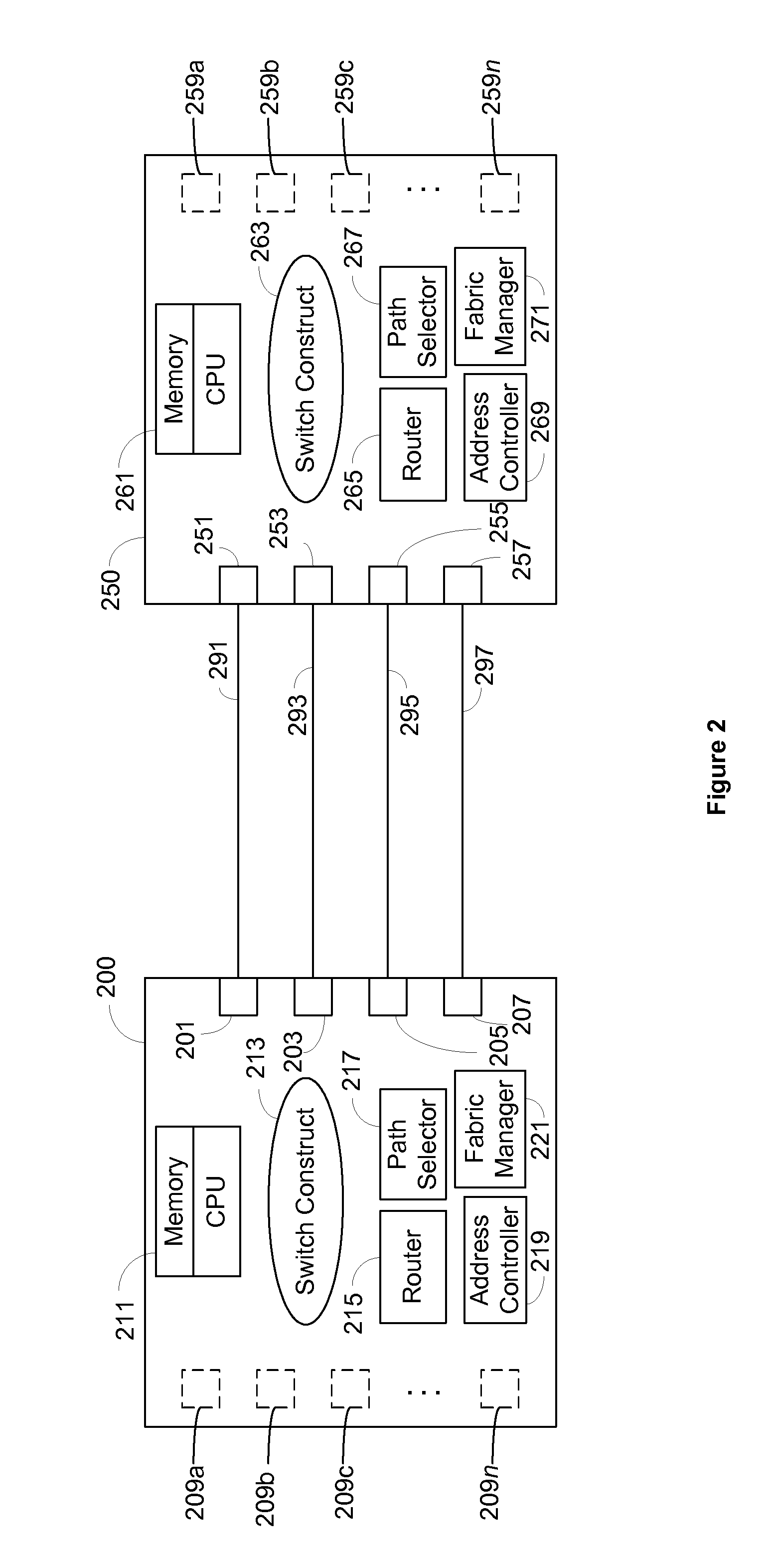
[0011]In one embodiment, the fabric can be configured with only one of the multiple parallel ISLs between any two switches. Fabric configuration can execute steps for selecting principal switch and exchanging switch parameters; distributing Domain IDs to each switch in the fabric; establishing zones; and performing path selection and establishing routes. Because the fabric configuration can be carried out without including the unselected ISLs and the associated ports, the peak computing resource requirement on each switch is considerably reduced. And because the available computing resources are expended in fabric configuration with only the selected ISLs, the fabric configuration time can be minimized.

Problems solved by technology

However, parallel ISLs require multiple resources for the initialization of the associated switch ports.
Performing bringing up or initialization of each port associated with the ISLs requires considerable computing resources in the form of CPU cycle time and memory.
Therefore, when a large number of ports are brought up at the same time, the peak resources requirement is very large.
However, once the ports have been brought up and the switch has been brought to steady state operation, the need for resources declines considerably (typically by an order of magnitude).
Therefore it still does not address the problem of high peak resource requirements during port bring up.
Unfortunately, because faster fabric configuration is highly desirable, users are forced to select switching elements that have been designed for peak resource requirements—resulting in increased cost and complexity of the system, while at the same time resulting in underutilized computing resources after the transient peak requirements have receded.
But this method requires manual intervention and takes even longer to bring up the network.

Method used


Image

  • Staged Port Initiation of Inter Switch Links
  • Staged Port Initiation of Inter Switch Links
  • Staged Port Initiation of Inter Switch Links

Examples


Embodiment Construction

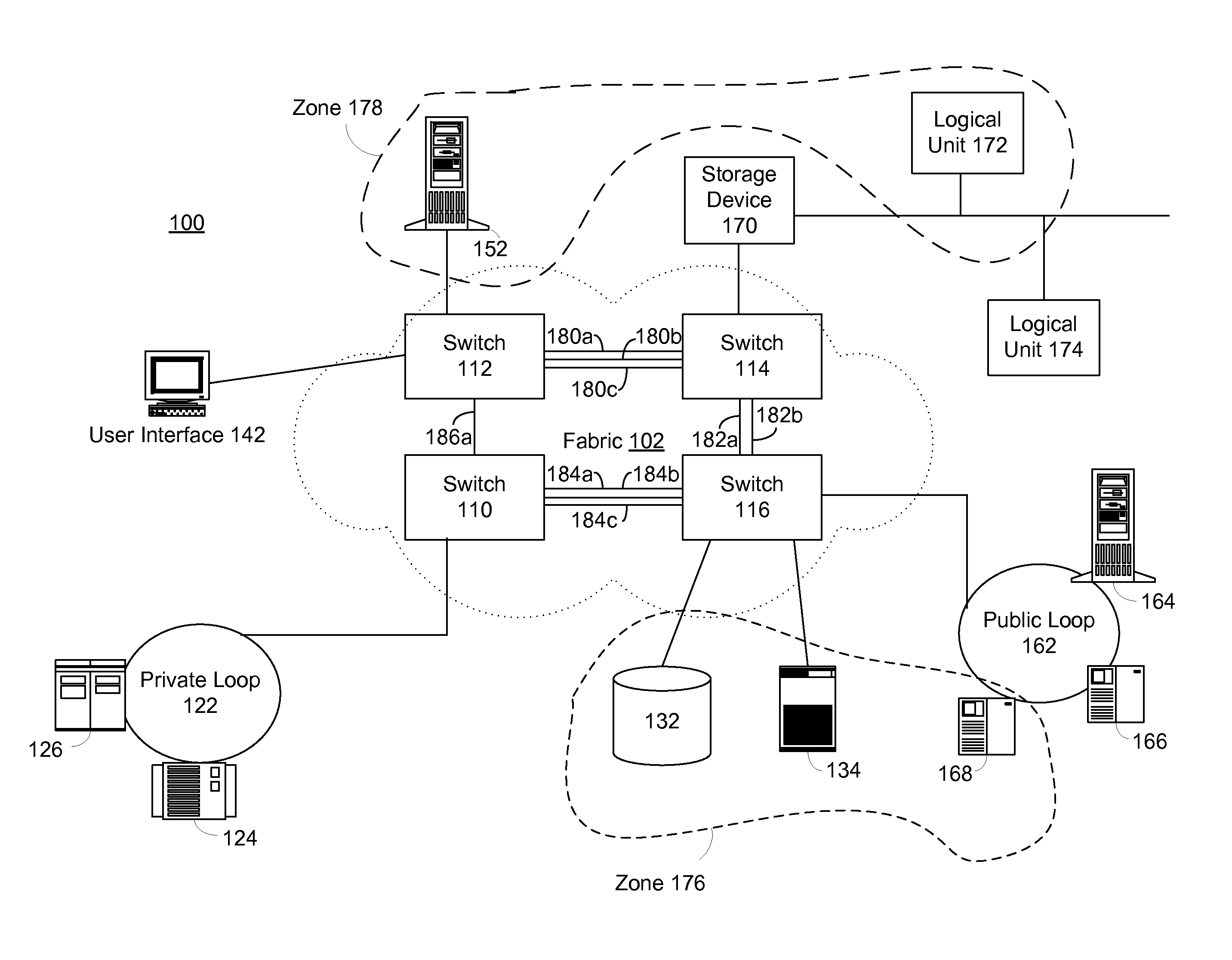
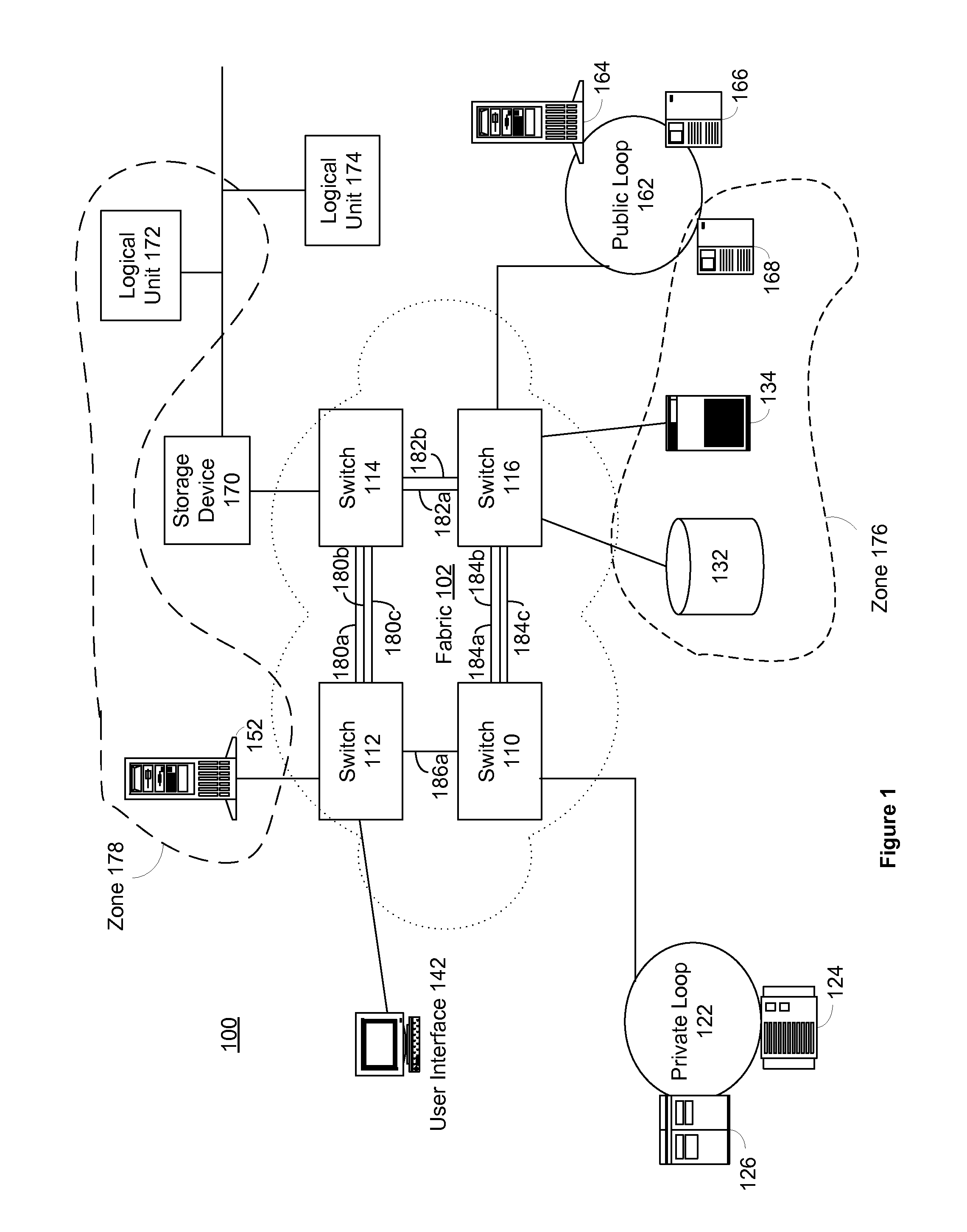
[0019]FIG. 1 illustrates a Fibre Channel network 100 including various network, storage, and user devices. Generally, the network 100 can be connected using Fibre Channel connections (e.g., optical fiber and coaxial cable). In the embodiment shown and for illustrative purposes, the network 100 can include a fabric 102 comprised of four different switches 110, 112, 114, and 116. It will be understood by one of skill in the art that a Fibre Channel fabric may be comprised of one or more switches.

[0020]A variety of devices can be connected to the fabric 102. A Fibre Channel fabric can support both point-to-point and loop device connections. A point-to-point connection is a direct connection between a device and the fabric. A loop connection is a single fabric connection that supports one or more devices in an “arbitrated loop” configuration, wherein signals travel around the loop through each of the loop devices. Hubs, bridges, and other configurations may be added to enhance the conne...


PUM


Abstract

A fabric having switches interconnected with multiple parallel interswitch links can be configured using staged port bring up. Only one of the multiple parallel interswitch links between any two switches and the corresponding switch ports can be selected and initialized. The fabric can be configured with the selected ISLs. Once the fabric has stabilized, unselected ISLs and the corresponding switch ports can be incrementally initialized. The number of unselected ISLs to be initialized can be determined based on the available computing resources of the fabric switches.

Description

BACKGROUND OF THE INVENTION[0001]1. Field of the Invention[0002]The present invention relates generally to storage area networks. Particularly, the present invention relates to initialization of inter-switch links.[0003]2. Description of the Related Art[0004]Storage networks can comprise several Fibre Channel switches interconnected in a fabric topology. These switches are interconnected by a number of inter-switch links (ISLs), which carry both data and control information. The control path provides connectivity among the switching elements and presents the fabric as a single entity to the end devices. The data paths provide throughput to the end devices connected to the fabric.[0005]For higher throughput, switching elements are often interconnected with parallel redundant ISLs. ISLs terminate at switch ports connected to each switch. These parallel ISLs between a pair of switches can be treated as a single logical interconnection with increased bandwidth. In addition, the increase...

Claims


Application Information

Patent Timeline
IPC IPC(8): H04L12/28H04L12/26H04L12/56H04L45/243
CPCH04L41/0806H04L49/15H04L45/245H04L43/0817H04L41/344
Inventor WUSIRIKA, BALAKRISHNA
Owner AVAGO TECH INT SALES PTE LTD
Learn More