Spinal implant with a flexible extension element

a technology of flexible extension and spinal implant, which is applied in the field of spinal connection devices, can solve the problems of difficult or impossible placement of spinal fixation rods one or more vertebrae may be out of alignment, and difficult or impossible to place the spinal fixation rod through each bone anchor head

Active Publication Date: 2011-04-21
DEPUY SYNTHES PROD INC
View PDF56 Cites 65 Cited by
  • Summary
  • Abstract
  • Description
  • Claims
  • Application Information

AI Technical Summary

Benefits of technology

[0008]The locking cap may slide along at least one of the elongated extension elements. The locking cap may be lowered toward the head cap to stabilize the spinal fixation element therebetween using the elongated extension elements. Alternatively, the locking cap may be lowered toward the head cap using a set screw. The set screw may be coupled to the locking cap. The elongated extension elements keep some of the soft tissue around the surgical site away from the surgical site to provide clearance for the spinal fixation element. Thus, the surgeon may have better access to the surgical site and may controllably implant the spinal fixation element. The elongated extension elements may stick out of the surgical site. A portion of the elongated extension elements is removed upon placing the spinal fixation element in a desired position.
[0011]According to other aspects of the present invention, the spinal implant may further include a plurality of reduction features provided on at least one of the first elongated extension element and the second elongated extension element. The plurality of reduction features provide a controlled movement of the anchor head cap along at least one of the first elongated extension element and the second elongated extension element. The controlled movement prevents the anchor head cap from sliding along the first elongated extension element or the second elongated extension element.
[0013]According to various aspects, the method may also include removing a portion of the first extension element and / or the second extension element. The locking cap may be lowered using the first elongated extension element and the second elongated extension element. The spinal fixation element may be provided at a distance above the seat portion of the head cap. The locking cap stabilizes the spinal fixation element in place. The first elongated extension element and the second elongated extension element may be flexible.

Problems solved by technology

Thus the placement of the spinal fixation element into the bone anchor head becomes very challenging.
This is especially problematic in extended constructs where multiple vertebral bodies are being fixated.
Additionally, in many instances one or more vertebrae may be out of alignment such that the one or more vertebrae and the inserted bone anchor are not immediately adjacent to the inserted spinal rod or the bone anchors do not have comparable heights.
In these cases, since the spinal fixation rod cannot follow a well aligned path, it becomes challenging or impossible to place the spinal fixation rod though each bone anchor.
Specifically, in percutaneous or minimally invasive procedures, it is more difficult to adjust a spinal rod using a technique such as bending to make contact between the spinal rod and the bone anchors.
It is also more difficult to move such vertically or laterally displaced vertebrae so that the vertebrae may be coupled to the spinal rod.
Additionally, the current extension elements used in MIS procedures cause other logistical issues for the procedure.
Extension elements that crowd the incision area add complexity to the operation.
The time required managing assembling the extensions elements and disengaging them may be extensive.

Method used


Image

  • Spinal implant with a flexible extension element
  • Spinal implant with a flexible extension element
  • Spinal implant with a flexible extension element

Examples


Embodiment Construction

[0029]Embodiments of the present invention may provide an improved spinal implant with a profile that is lower than standard spinal implants to be used in minimally invasive surgeries. The spinal implant may include at least one flexible elongated extension element. The spinal implant may allow for controlled placement of a spinal fixation element. One skilled in the art will recognize that the invention is not limited to use in bone or in spinal surgery, and that the spinal implant and methods described herein can be adapted for use with any suitable surgical device to be moved into a selected position in a variety of medical procedures.

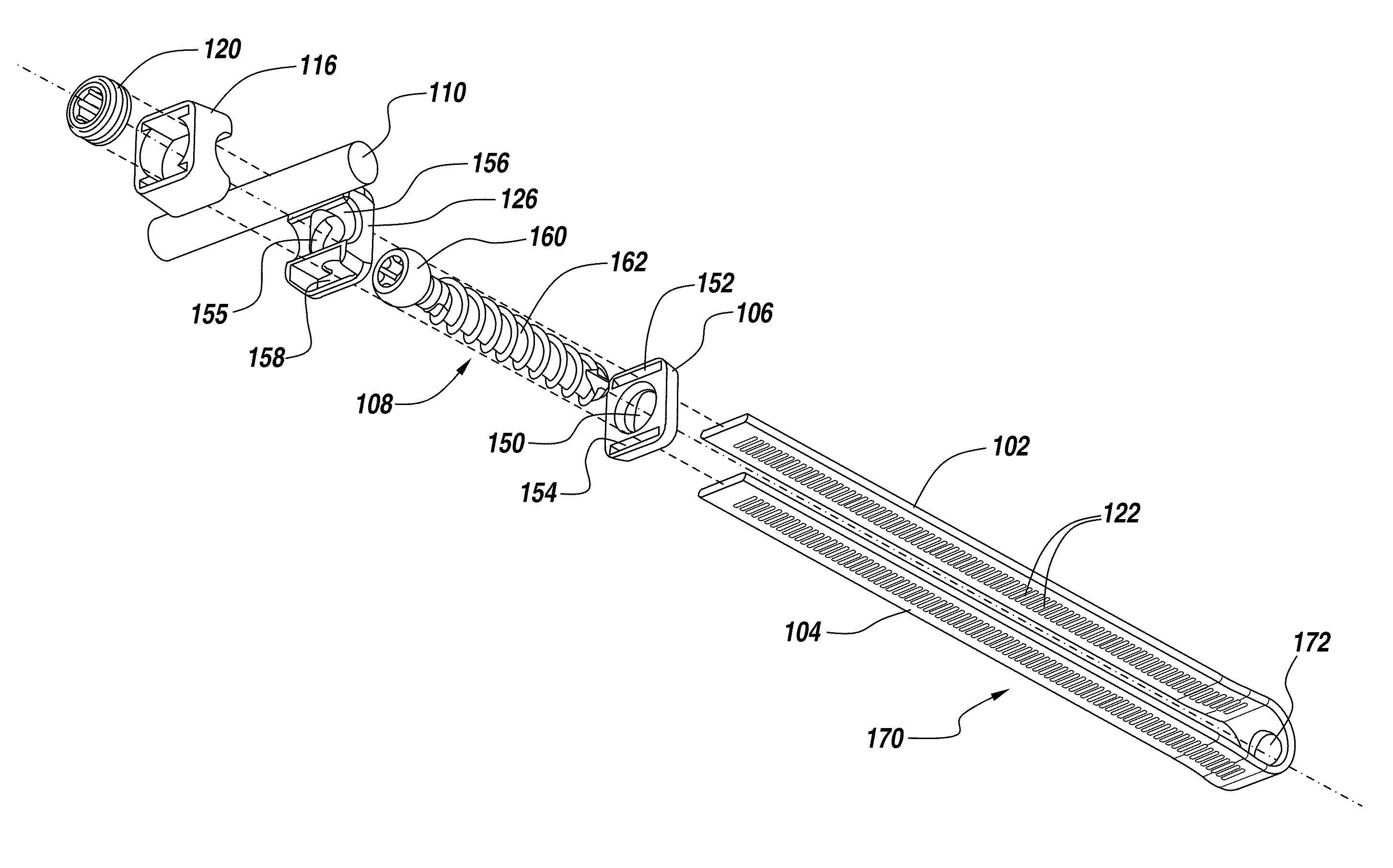
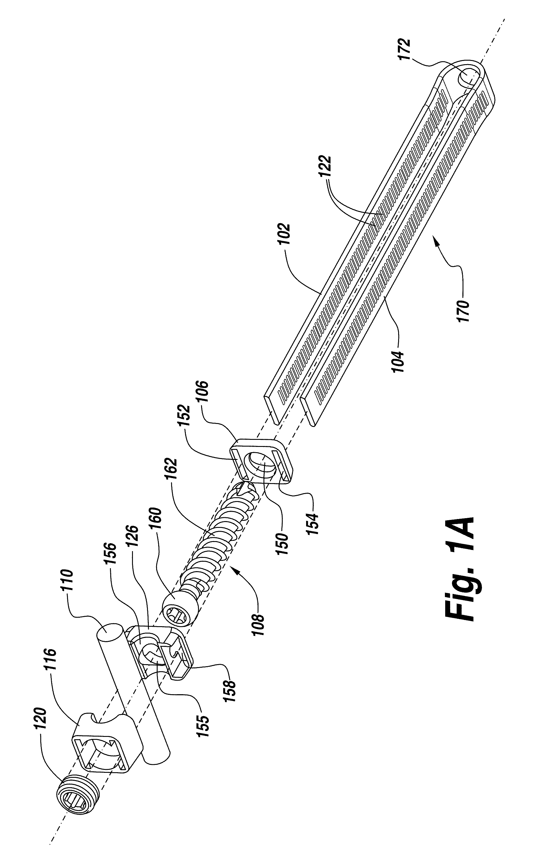
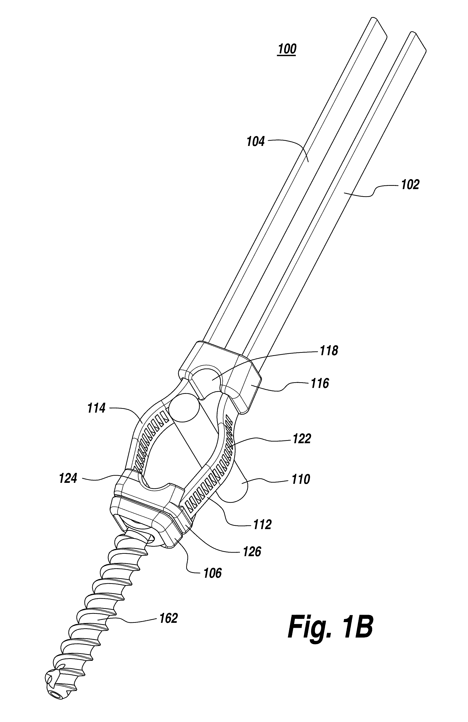
[0030]FIGS. 1A-1F illustrate an exemplary spinal implant 100. The spinal implant 100 includes a poly-axial or mono-axial screw 108. The screw 108 includes a head portion 160 and a shaft 162 extending away from the head portion 160 along a longitudinal axis of the screw 108. The shaft 162 of the screw 108 engages a bone while the head portion 160 of ...


PUM


Abstract

A spinal implant with at least one flexible elongated extension element is provided. The spinal implant has a profile that is lower than standard spinal implants. The spinal implant includes a bone anchor with a head portion and a shaft extending along a longitudinal axis of the bone anchor. A head plate is coupled to the bone anchor. The head plate includes a first elongated extension element and a second elongated extension element. The first elongated extension element and the second elongated extension element may be formed as a single monolithic element that is attached to the head plate by passing through a pair of openings provided on the head plate. At least one of the first elongated extension element and the second elongated extension element is flexible.

Description

FIELD OF THE INVENTION[0001]The present invention relates to spinal connection devices used in orthopedic surgery. More particularly, the present invention relates to a spinal implant with at least one flexible elongated extension element.BACKGROUND OF THE INVENTION[0002]Spinal fixation systems may be used in surgery to align, adjust and / or fix portions of the spinal column, i.e., vertebrae, in a desired spatial relationship relative to each other. Many spinal fixation systems employ a spinal rod, i.e. a spinal fixation element, for supporting the spine and for properly positioning components of the spine for various treatment purposes. The fixation system components, such as vertebral anchors, comprising pins, bolts, screws, and hooks, engage the vertebrae and connect the supporting rod to different vertebrae. The spinal fixation system components can have a predetermined contour that has been designed according to the properties of the target implantation site. Once installed, the...

Claims


Application Information

Patent Timeline
Patent Type & Authority Applications(United States)
IPC IPC(8): A61B17/70A61B17/86A61B17/88
CPCA61B17/7032A61B17/7037A61B17/7053A61B2019/307A61B2017/00867A61B17/7076A61B2017/567A61B2017/681A61B2090/037
Inventor RAMSAY, CHRISTOPHER L.DZIEDZIC, SARAMAHONEY, MICHAEL
Owner DEPUY SYNTHES PROD INC
Why Eureka
Try Eureka