Methods and apparatus for control configuration with enhanced change-tracking

a technology of change tracking and control configuration, applied in the field of process control, can solve the problems of driving pressure and boiling activity upwards, and typically have neither computing power nor user interfaces required

Active Publication Date: 2011-04-21
SCHNEIDER ELECTRIC SYST USA INC
View PDF108 Cites 47 Cited by
  • Summary
  • Abstract
  • Description
  • Claims
  • Application Information

AI Technical Summary

Benefits of technology

[0025]These live devices are, for example, those that are actively coupled to the network and on which a user is logged-in (or in which a process capable of effecting the change is active)—or that, more generally, are sufficiently coupled to the changed as to enable a user (or process) to effect the change to the configurable elements.
[0026]In such a control system, by way of non-limiting example, the change detection system can respond to a change (e.g., made outside the configurator) by querying the network for a list of devices that are active and logged in to the control network to identify those capable of effecting a configuration changes. The change detection system can, further, winnow down the live list to identify workstations, personal computers, portable computers, personal digital assistants and other devices on which a logged-in user might effect the detected change. It can further include, of example, winnowing such a list to identify (a) devices from which a change is expected to be made (e.g., a plant floor-based workstation, and / or (b) unexpected devices from which a surreptitious change might be made (e.g., an unregistered portable computer or PDA).

Problems solved by technology

If the vessel pressure is too low, the control algorithm may call for incrementally opening the heating gas valves, thereby, driving the pressure and boiling activity upwards.
They typically have neither the computing power nor user interfaces required to facilitate the design of a control algorithm.

Method used


Image

  • Methods and apparatus for control configuration with enhanced change-tracking
  • Methods and apparatus for control configuration with enhanced change-tracking
  • Methods and apparatus for control configuration with enhanced change-tracking

Examples


Embodiment Construction

System Architecture

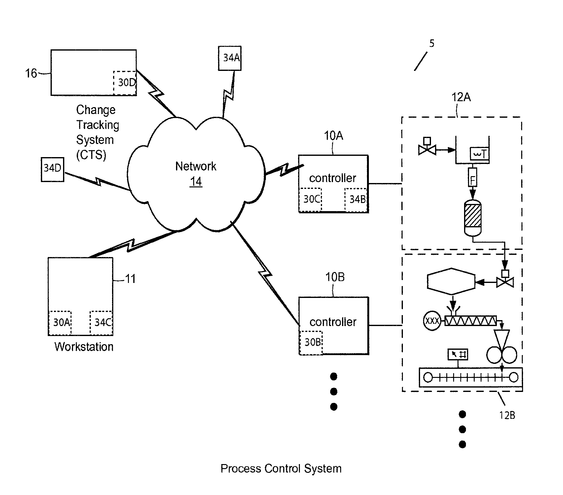
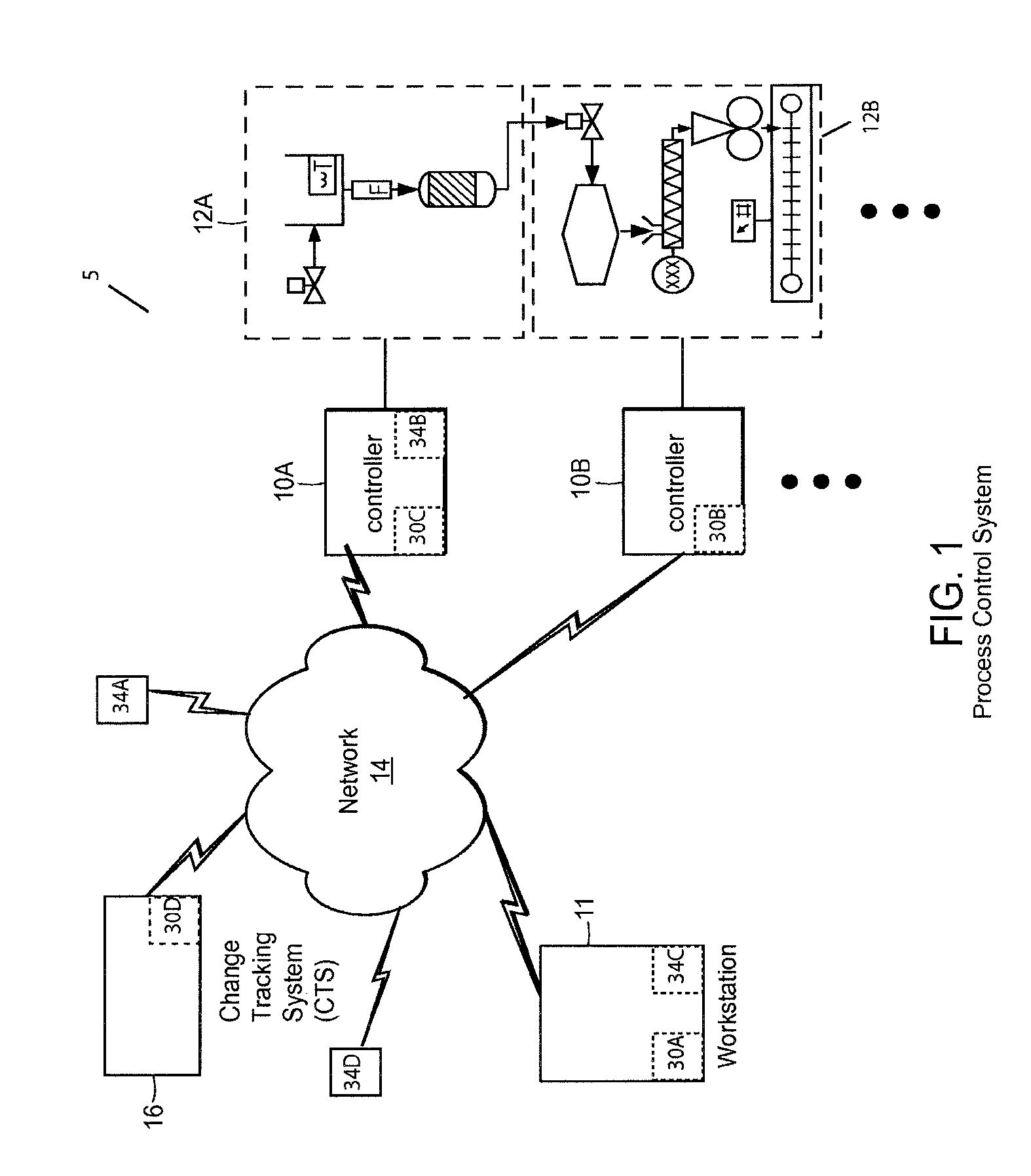
[0039]FIGS. 1-2 depict an illustrative control system 5 of the type with which apparatus and methods according to the invention may be practiced. The illustrated system is particularly adapted for use in connection with process control, as discussed further below. However, those skilled in the art will appreciate that apparatus and methods according to the invention can be used in connection with other control systems. In this regard, subsystems 12A, 12B can encompass any industrial, manufacturing, service, environmental or other process, device or system under monitoring or control (hereinafter, collectively, “control”).

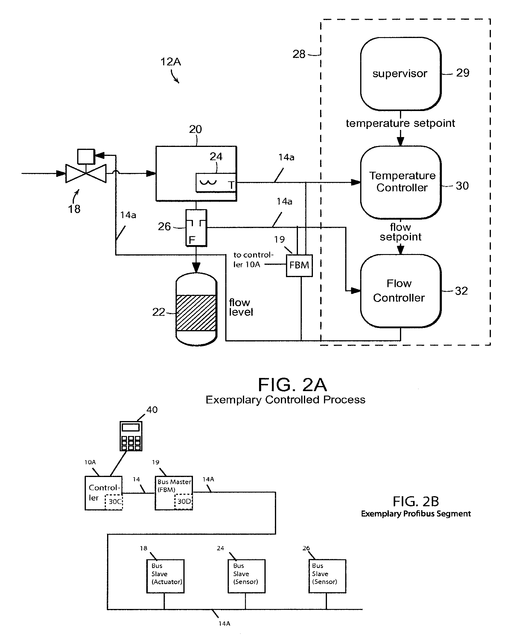
[0040]The system of FIGS. 1-2 includes a workstation 11 that is coupled to one or more control devices, here, controllers 10A, 10B, actuators 18, sensors 24, 26, and so forth, as illustrated, on some of which reside process control algorithms for monitoring and / or controlling one or more processes within subsystems 12A, 12B. These may represent in...


PUM


Abstract

The invention provides, in some aspects, a process, environmental, manufacturing, industrial or other such control system (hereinafter, “control system”) with enhanced, real-time change tracking. The system includes one or more configurable elements (e.g., field devices), a change tracking system that records of changes to those configurable elements (e.g., for compliance reporting, etc.) and a change detection system that responds to detected changes in configuration of those element(s) by inferring an identity of a person and/or device responsible for a change, the time of the change, and/or the reason for the change. This is unlike prior art systems, in which that such information must be specified, e.g., in a data entry form filled-in by the field engineer, operator or other who is making the change.

Description

REFERENCE TO RELATED APPLICATIONS[0001]This application is a continuation-in-part of U.S. patent application Ser. No. 12 / 474,942, filed May 29, 2009, entitled “Methods And Apparatus For Control Configuration With Control Objects That Are Fieldbus Protocol Aware,” and U.S. patent application Ser. No. 12 / 474,885, filed May 29, 2009, entitled “Methods And Apparatus For Control Configuration With Control Objects That Self-Define Tracked. Parameters,” the teachings of both of which are incorporated herein by reference.[0002]This application is related to U.S. patent application Ser. No. 12 / 265,837, filed Nov. 6, 2008, entitled “Apparatus for Control Systems with Objects that Are Associated with Live Data,” which is a continuation of U.S. application Ser. No. 12 / 247,872, filed Oct. 8, 2008 and entitled “CONTROL SYSTEM EDITOR AND METHODS WITH LIVE DATA”, which is a continuation of U.S. application Ser. No. 11 / 434,005, filed May 15, 2006 and entitled “METHOD AND APPARATUS FOR CONTROL CONFIG...

Claims


Application Information

Patent Timeline
Patent Type & Authority Applications(United States)
IPC IPC(8): G05B19/042
CPCG05B19/042G05B2219/23299G05B23/0297G05B2219/25061G05B2219/24168
Inventor KOSTADINOV, VLADIMIRELDRIDGE, KEITH E.
Owner SCHNEIDER ELECTRIC SYST USA INC
Why Eureka
Try Eureka