Portable Cyclonic Dust Collector/Vacuum Cleaner

a cyclonic dust collector and vacuum cleaner technology, applied in the direction of auxillary pretreatment, cleaning filter means, separation processes, etc., can solve the problems of limiting air flow, health hazards, and serious quality issues, and achieve the effect of high energy efficiency and simplified design

Active Publication Date: 2011-04-28
WITTER ROBERT M
View PDF40 Cites 45 Cited by
  • Summary
  • Abstract
  • Description
  • Claims
  • Application Information

AI Technical Summary

Benefits of technology

[0007]Accordingly, it is an object of this invention to create a combined vacuum and a high energy efficiency cyclonic separator so that the device has an efficient but simplified design, and avoids the drawbacks of the prior art.

Problems solved by technology

This airborne fine dust can present a health hazard, and in a wood shop environment airborne particulates constitute a serious quality issue as the airborne dust can contaminate varnish or other wood finishes.
The dust that is collected can quickly clog and blind the filter also, which limits air flow and diminishes the efficiency of the vacuum cleaner.
Moreover, filling of the filter material requires that the vacuuming operation be interrupted frequently for cleaning and / or replacing of the filter.
This arrangement exhausts significantly cleaner air back into the ambient, but because the air passes directly from the main collection drum out to the filter housing, the filter accumulates dust quickly and requires frequent cleaning for effective operation.
However, this arrangement requires attaching the cyclone as a separate element in between the shop vacuum cleaner and the dust producing tool or dust pick-up tool.

Method used


Image

  • Portable Cyclonic Dust Collector/Vacuum Cleaner
  • Portable Cyclonic Dust Collector/Vacuum Cleaner
  • Portable Cyclonic Dust Collector/Vacuum Cleaner

Examples


Embodiment Construction

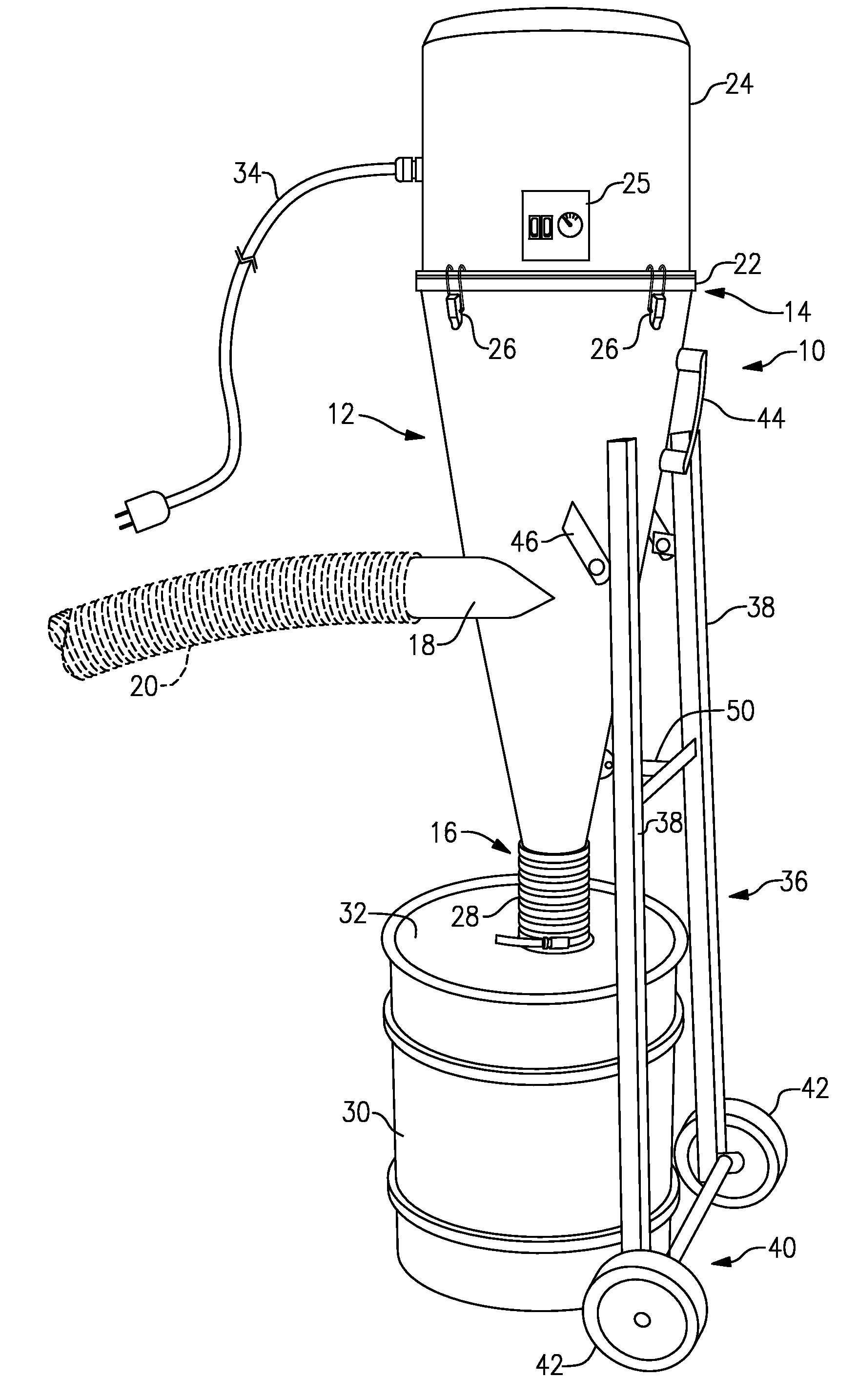
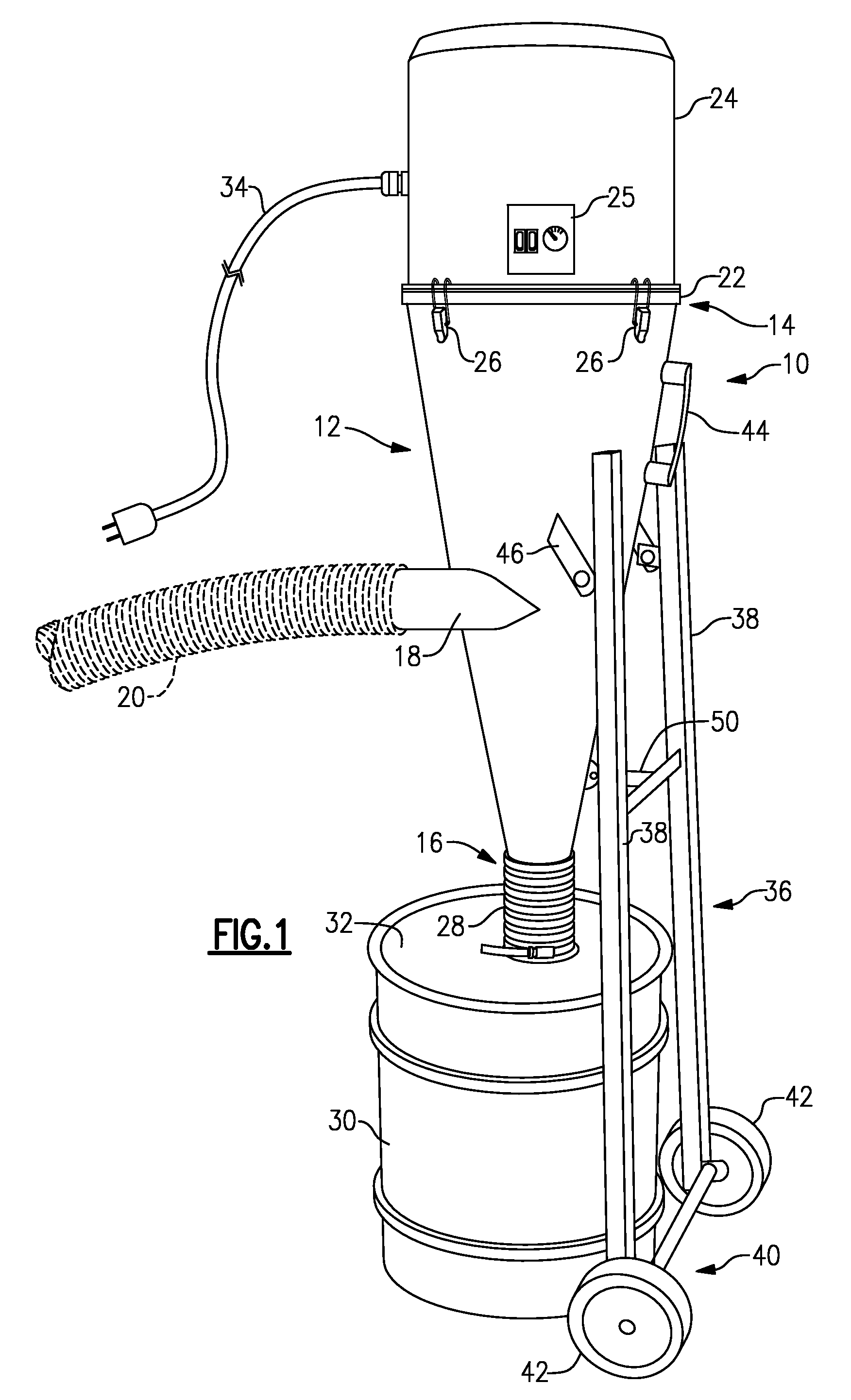
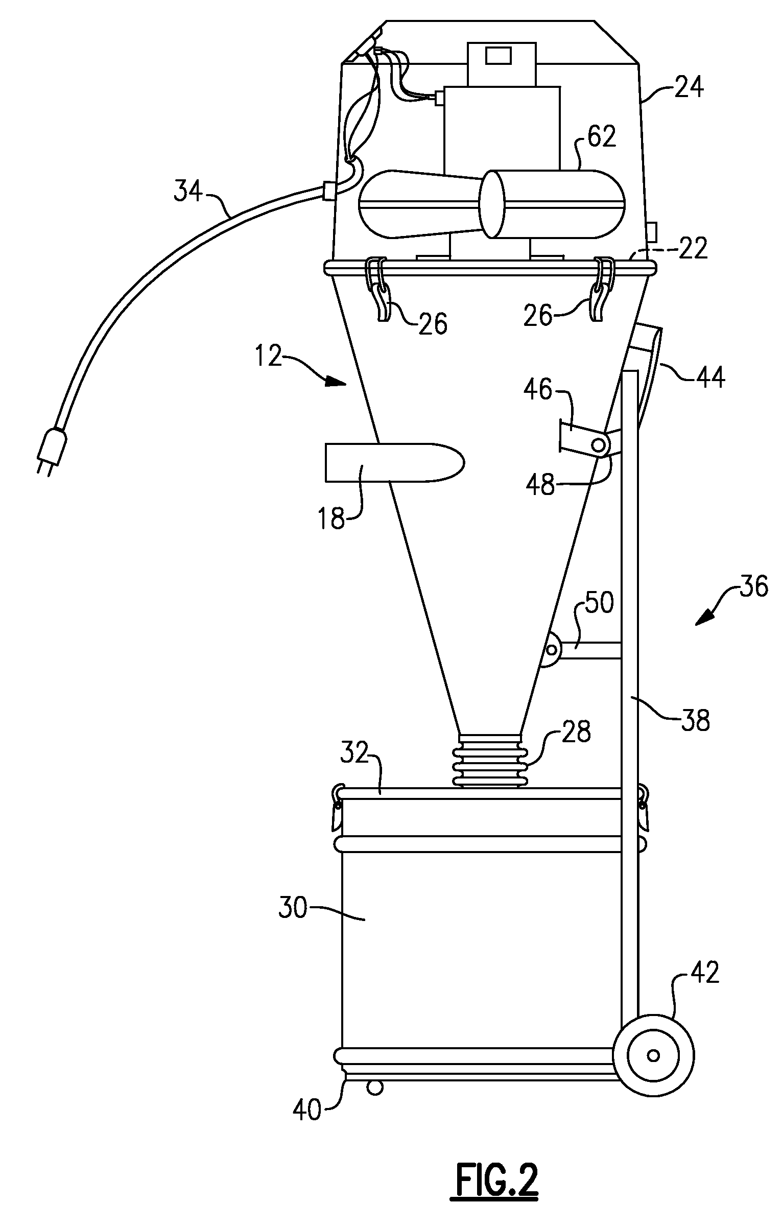
[0039]Now, with reference to the Drawing, FIGS. 1 to 3 show the portable cyclonic vacuum cleaner 10 according to an embodiment of this invention in which dust is cyclonically separated from the air flow, with the leaving air being cleaned in final filter and returned to the ambient as clean, filtered air.

[0040]The cyclonic vacuum cleaner 10 is based on conic body 12, that is, a cone-shaped shell with a mouth 14 or wide end at its top and a narrow nose 16 at its bottom end. An intake pipe 18 or air inlet penetrates the conic body 12 at a point about half-way between the mouth and the nose, and a flexible vacuum hose 20, here shown in broken line, is attached to the intake pipe 18. The hose 20 can be connected to a scoop or other vacuum cleaner tool, or may be connected to a dust producing tool or appliance, such as a sander or saw. In this embodiment, the hose 20 and intake pipe 18 have a nominal 2.5 inch diameter. The intake pipe or inlet 18 can be shouldered and tapered to allow it...


PUM

PropertyMeasurementUnit
diameteraaaaaaaaaa
diameteraaaaaaaaaa
heightaaaaaaaaaa

Abstract

A cyclonic portable vacuum cleaner/dust collector for workshop or other use has a conic body that is supported on a hand cart or dolly. A funnel shaped divider plate within the conic body divides it into a cyclonic chamber between the divider plate and the lower nose, and a filter chamber between the divider plate and a motor plate that closes the upper mouth of the conic body. The filter chamber contains a filter cartridge. A vacuum air pump is mounted on the motor plate, and is covered by a shroud or housing. Clean, filtered air is exhausted into the ambient. Process dust settled into a dust collection drum supported beneath the nose of the conic body. A pulse cleaning arrangement serves for periodic filter cleaning. The supporting cart can be wheeled or can use a wall bracket for wall mounting.

Description

BACKGROUND OF THE INVENTION[0001]This invention is directed to heavy-duty vacuum cleaners of the type intended for workshop use, such as in wood shops, machine shops, or for industrial applications, namely, a hybrid shop vacuum / dust collector, having a higher capacity (more CFM) than a standard shop vacuum. The invention is more particularly concerned with a heavy duty portable vacuum in which there are a two or more dust separation stages, with the large majority of the dust being separated cyclonically and deposited into a drum or barrel, and with the remaining dust that is carried in the vacuum machine air stream being filtered out in a final filter, so that the vacuum cleaner machine exhausts clean, filtered air into the ambient.[0002]Industrial vacuum cleaners and shop vacuum cleaners are often employed for picking up dust that has accumulated on the shop floor and on surfaces of equipment, or may also be connected to a dust outlet of a dust-producing tool, i.e., wood working m...

Claims


Application Information

Patent Timeline
Patent Type & Authority Applications(United States)
IPC IPC(8): A47L9/16
CPCB01D46/2411B01D50/002B04C2009/005B04C5/185B04C2009/002B04C5/04B01D50/20
Inventor WITTER, ROBERT M.
Owner WITTER ROBERT M
Why Eureka
Try Eureka