Pulse Filter Cleaner for Portable Cyclonic Dust Collector/Vacuum Cleaner

Active Publication Date: 2014-08-14
ONEIDA AIR SYST
View PDF2 Cites 12 Cited by
  • Summary
  • Abstract
  • Description
  • Claims
  • Application Information

AI Technical Summary

Benefits of technology

This patent describes a vacuum cleaner that combines a high-energy efficiency cyclonic separator with a reverse pulse mechanism for cleaning the filter cartridge. The device has an efficient but simplified design and does not impair or complicate its normal operation. The reverse pulse mechanism is operated by a simple lever, which returns to a normal mode as soon as the lever is released. It is designed to vacuum cleaner efficiently removes dust from the air stream, returning clean, filtered air to the ambient without the risk of starting a fire. Additionally, the vacuum cleaner can operate for an extended period without the need to unclog or clean the exhaust air final filter.

Problems solved by technology

This airborne fine dust can present a health hazard, and in a wood shop environment airborne particulates constitute a serious quality issue as the airborne dust can contaminate varnish or other wood finishes.
The dust that is collected can quickly clog and blind the filter also, which limits air flow and diminishes the efficiency of the vacuum cleaner.
Moreover, filling of the filter material requires that the vacuuming operation be interrupted frequently fto clean and / or replace the filter.
This arrangement exhausts significantly cleaner air back into the ambient, but because the air passes directly from the main collection drum out to the filter housing, the filter accumulates dust quickly and requires frequent cleaning for effective operation.
However, this arrangement requires attaching the cyclone as a separate element in between the shop vacuum cleaner and the dust producing tool or dust pick-up tool.

Method used


Image

  • Pulse Filter Cleaner for Portable Cyclonic Dust Collector/Vacuum Cleaner
  • Pulse Filter Cleaner for Portable Cyclonic Dust Collector/Vacuum Cleaner
  • Pulse Filter Cleaner for Portable Cyclonic Dust Collector/Vacuum Cleaner

Examples


Embodiment Construction

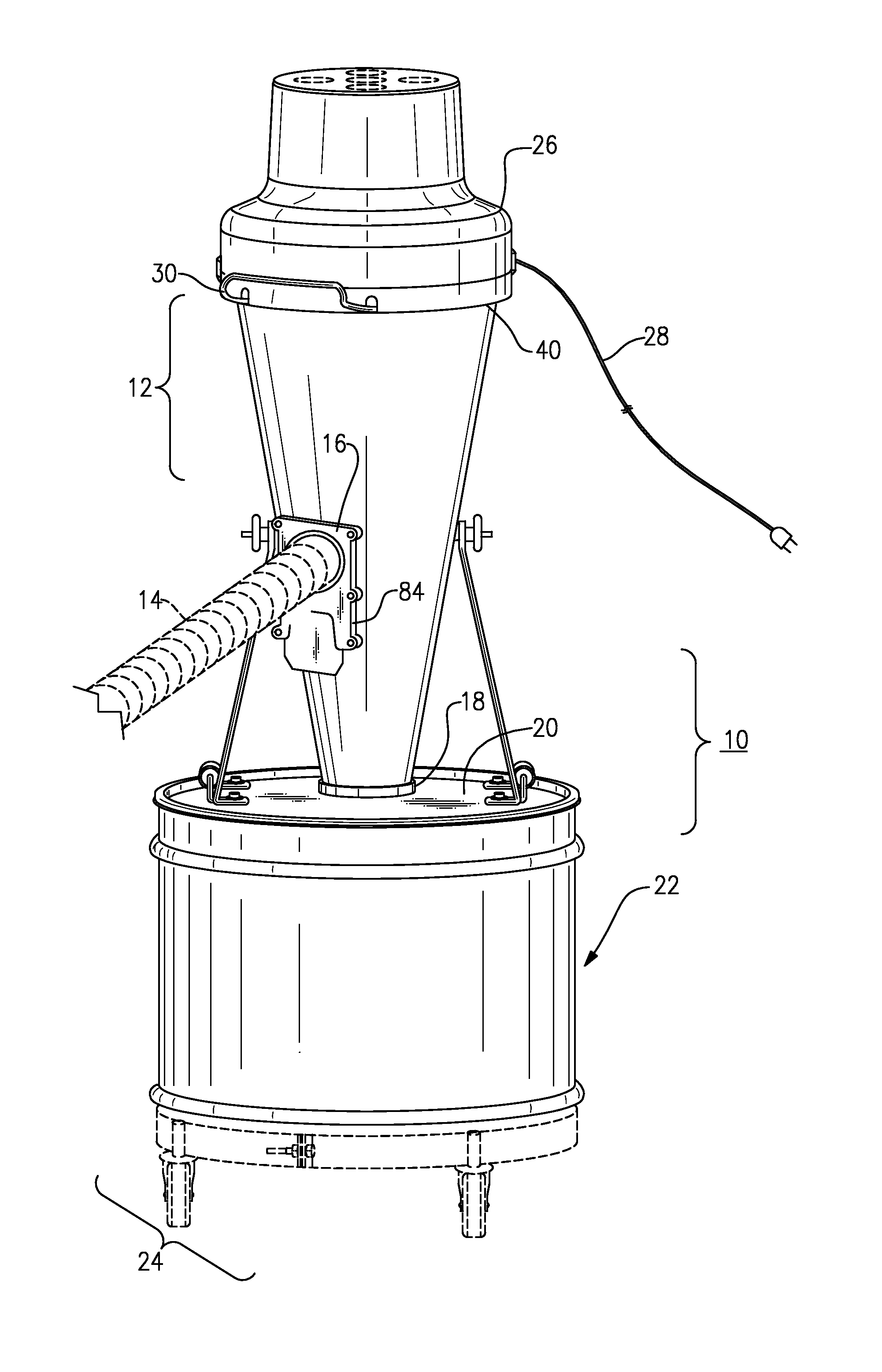
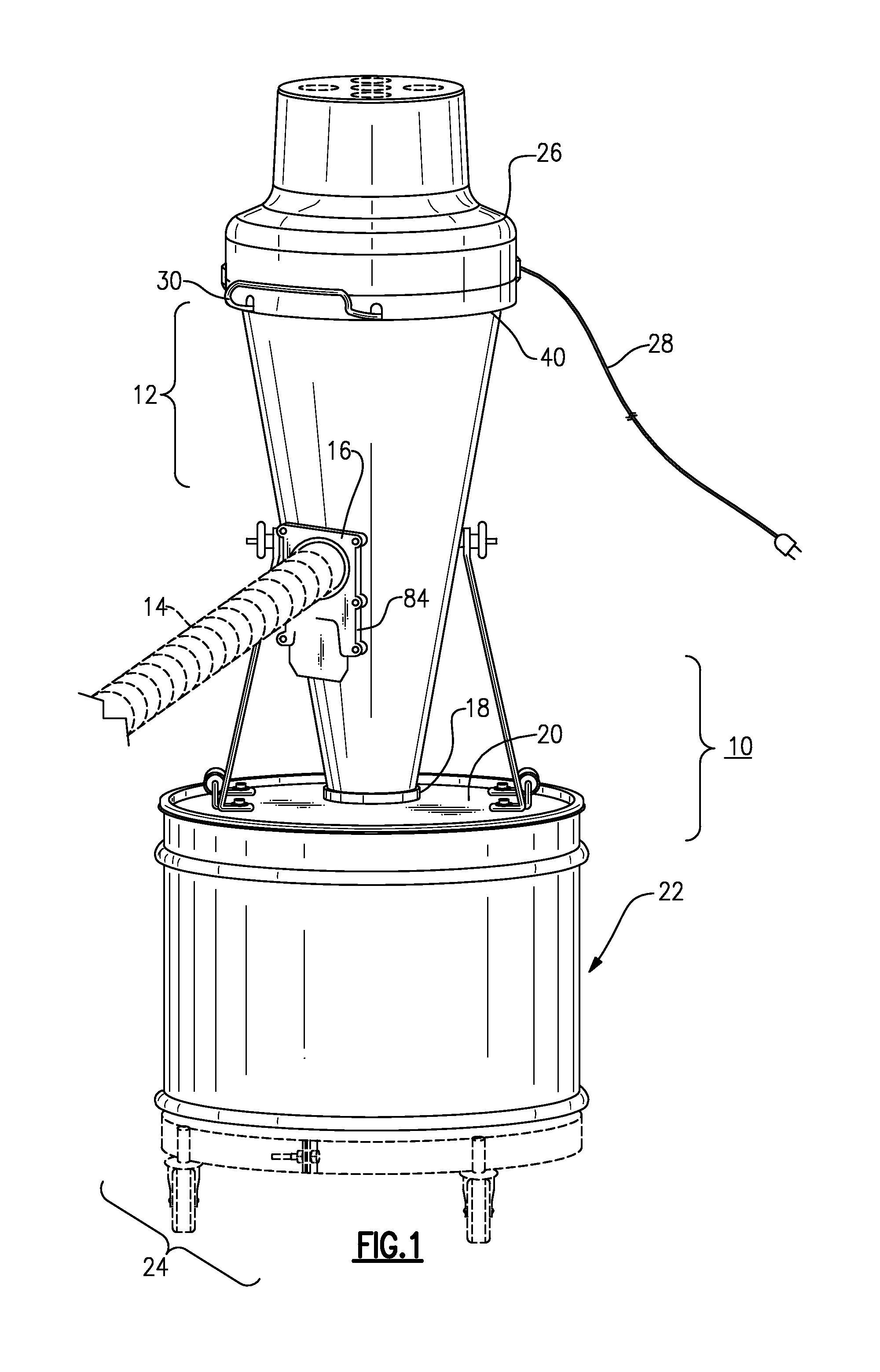
[0037]Now, with reference to the Drawing, and initially to FIGS. 1 and 2, a portable cyclonic vacuum cleaner 10 according to an embodiment of this invention gathers and separates dust cyclonically from the air flow in which the dust is entrained, with the leaving air being cleaned in a final filter and returned to the ambient as clean, filtered air.

[0038]The cyclonic vacuum cleaner 10 is based on conic body 12, that is, a cone-shaped shell with a mouth or wide end at its top and a narrow nose at its bottom end. A vacuum hose 14 is attached onto an intake pipe 16 or air inlet penetrates the conic body 12 at a point about half-way between the mouth and the nose. The hose 14 can be connected to a scoop or other vacuum cleaner tool, or may be connected to a dust producing tool or appliance, such as a sander or saw. In this embodiment, the hose 14 and intake pipe 16 have a nominal 2.5 inch diameter. The intake pipe or inlet 16 can be shouldered and tapered to allow it to accommodate a wi...


PUM

PropertyMeasurementUnit
Pressureaaaaaaaaaa
Flow rateaaaaaaaaaa

Abstract

A cyclonic portable vacuum cleaner / dust collector has a cyclonic chamber and a filter chamber. The filter chamber contains a filter cartridge with a hollow core positioned over the discharge opening of a motor plate that closes the filter chamber. A vacuum blower is mounted on the motor plate, with an intake tube at the discharge opening of the motor plate. An annular pulse-cleaning plate is positioned over an associated annular opening that surrounds the motor plate discharge opening and has an open center that slides up and down on the intake tube of the vacuum blower. A bail handle or lever extends from the pulse-cleaning plate to a handle portion outside the cover or shroud. The handle is pushed down to lift the pulsing plate to provide a reverse pressure air pulse to the filter to blast off accumulated dust. An anti-deflagration screen may be present at the center of the motor plate.

Description

[0001]This is a continuation-in-part of pending application Ser. No. 12 / 607,122, filed Oct. 28, 2009, and of pending application Ser. No. 13 / 029,243, filed Feb. 11, 2011, which claims priority under 35 USC 119(e) of provisional patent applications Ser. No. 61 / 306,056, filed Feb. 19, 2010 and Ser. No. 61 / 315,695, filed Mar. 19, 2010. The disclosures of these are incorporated by reference herein.BACKGROUND OF THE INVENTION[0002]This invention may be embodied in heavy-duty vacuum cleaners of the type intended for workshop use, such as in wood shops, machine shops, or for industrial applications, namely, a hybrid shop vacuum / dust collector, having a higher capacity (more CFM) than a standard shop vacuum. The invention is more particularly concerned with an improvement in a heavy duty portable vacuum in which there are a two or more dust separation stages, with the large majority of the dust being separated cyclonically and deposited into a drum or barrel, and with the remaining dust tha...

Claims


Application Information

Patent Timeline
IPC IPC(8): A47L9/16
CPCA47L9/1666A47L9/20B04C2009/002B01D46/0093B01D46/71
Inventor WITTER, ROBERT A.HILL, JEFFREYFITZSIMMONS, JOHN J.
Owner ONEIDA AIR SYST
Why Eureka
Try Eureka