Hydraulic cylinder cushion device with check ring

a cushion device and hydraulic cylinder technology, applied in positive displacement engines, reciprocating piston engines, engines without rotary main shafts, etc., can solve the problems of time delay until, delay in discharge side of the pump, and possibility of damage due to stress concentration, so as to prevent the effect of initial abrupt operation, preventing excessive pressure increase of the pump, and preventing the operation of the stroke end

Active Publication Date: 2011-04-28
VOLVO CONSTR EQUIP
View PDF2 Cites 1 Cited by
  • Summary
  • Abstract
  • Description
  • Claims
  • Application Information

AI Technical Summary

Benefits of technology

[0017]First, the check ring is formed, and thus the operation delay in the stroke end and the initial abrupt operation can be prevented.
[0018]Second, since the excessive pressure increase of the pump due to the operation delay in the stroke end can be prevented, the pump efficiency is heightened.
[0019]Third, since the check ring is applied, the cushion function is additionally improved during the entrance into the stroke end, the excessive operation of the pump is prevented, and the operation delay is improved to heighten the fuel efficiency with the cost saved.

Problems solved by technology

Accordingly, a time delay occurs until the pressure is accumulated and a sufficient force is formed.
In this case, however, since a groove process is performed with respect to one end of the rod, which copes with a relatively great force and is exposed at all times, there is possibility of damage due to the stress concentration.
From the viewpoint of the hydraulic system, as shown in FIG. 3, when the cylinder is initially operated at the stroke end, the operation of the discharge side of the pump is delayed due to the insufficiency of a pressed area in the cylinder, and thus the pressure is increased.
Sometimes, the increased pressure reaches the relief pressure, and this cause unnecessary energy consumption.
From the viewpoint of the cylinder operation, an instantaneous initial abrupt operation or the like occurs after the operation delay, and this causes a deathblow to the performance of the cylinder in the case where an elaborate work is required.
In addition, the above-described phenomenon aggravates fuel economy of the equipment due to the unnecessary energy consumption, and in order to give smooth initial operability, the phenomenon causes a system overdesign element such as an increase of pump capacity or the like to increase the cost.

Method used


Image

  • Hydraulic cylinder cushion device with check ring
  • Hydraulic cylinder cushion device with check ring
  • Hydraulic cylinder cushion device with check ring

Examples


Embodiment Construction

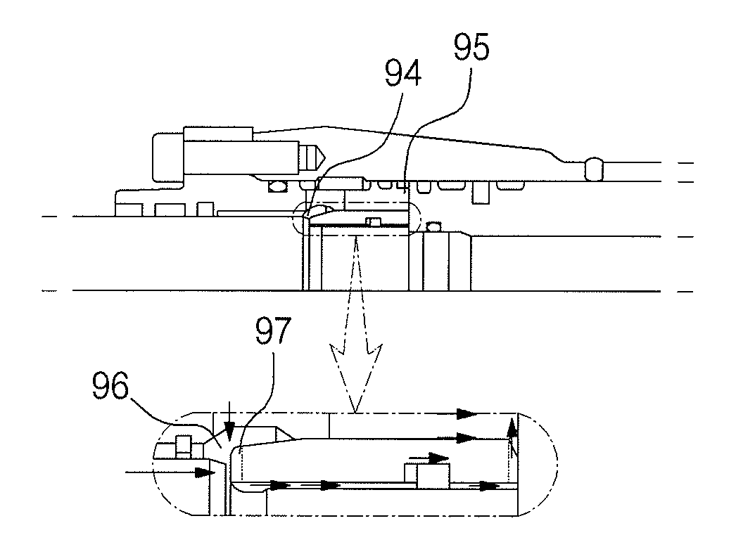
[0027]Hereinafter, a hydraulic cylinder cushion device according to preferred embodiments of the present invention will be described with reference to the accompanying drawings. In the drawings, thicknesses of lines, sizes of the constituent elements, or the like may be exaggerated for clarity in explanation.

[0028]Also, the spatially defined wordings in consideration of the functions of the present invention may differ in accordance with a user's or operator's intention or custom, and the definition of such wordings should be made based on the contents throughout the entire description of the present invention.

[0029]In addition, the matters defined in the description, such as the detailed construction and elements, are nothing but specific details provided to assist those of ordinary skill in the art in a comprehensive understanding of the invention, and thus the embodiments including constituent elements which are included in the entire description of the present invention and are ...


PUM


Abstract

A hydraulic cylinder cushion device installed in a hydraulic cylinder provided, in which a rod performs reciprocating movement in a cylinder tube, and which discharges high-pressure hydraulic fluid that is formed in pressure chambers between a piston and a head cover and between the piston and a cover end during a stroke-end operation. The hydraulic cylinder cushion device includes a check ring which is installed in a groove provided on an inner surface of the head cover or the cover end, and moves to one side in the groove so as to close a flow path during rushing into a stroke end while it moves to the other side in the groove so as to open the flow path during an initial operation in the stroke end.

Description

CROSS-REFERENCE TO RELATED APPLICATION[0001]This application is based on and claims priority from Korean Patent Application No. 10-2009-102767, filed on Oct. 28, 2009 in the Korean Intellectual Property Office, the disclosure of which is incorporated herein in its entirety by reference.BACKGROUND OF THE INVENTION[0002]1. Field of the Invention[0003]The present invention relates to a hydraulic cylinder cushion device, and more particularly to a hydraulic cylinder cushion device that improves the cushion performance at a stroke end by a check ring.[0004]2. Description of the Prior Art[0005]FIGS. 1A to 1C are views illustrating an example of a hydraulic pneumatic cylinder in the related art. As shown in FIG. 1A, a cylinder briefly includes a tube 10 which serves as a pressure vessel and guides a rectilinear movement of a piston, a rod 20 which is a long circular bar shaped shaft portion that performs a rectilinear reciprocating movement; a head cover 30 having a packing mounted thereon...

Claims


Application Information

Patent Timeline
Patent Type & Authority Applications(United States)
IPC IPC(8): F15B15/22
CPCF15B15/222F15B15/14F15B20/00
Inventor CHUNG, YUN HYUN
Owner VOLVO CONSTR EQUIP
Why Eureka
Try Eureka