Gravity anchor

a gravity anchor and anchor technology, applied in the field of anchors, can solve the problems of increasing the difficulty of handling it offshore, the need for aht's is compounded, and the crane capacity of tugs (aht's) may not be sufficient to handle these heavy gravity anchors, so as to improve the drag and hold power

Inactive Publication Date: 2011-04-28
J RAY MCCDERMOTT SA
View PDF6 Cites 5 Cited by
  • Summary
  • Abstract
  • Description
  • Claims
  • Application Information

AI Technical Summary

Benefits of technology

[0009]The present invention is drawn to a gravity anchor that includes one or more units. The units are designed to be rotationally linked together so that multiple units can be used to provide the required weight. The units are designed for ease of handling on the vessel and to control the rotation of the units relative to each other to insure proper orientation on the seafloor. The units are designed to help them dig into the sea bed and enhance the drag and holding power.

Problems solved by technology

However, the higher the weight of the gravity anchors, the more difficult it becomes to handle it offshore.
Often, the tugs (AHT's) may not have the required crane capacity to handle these heavy gravity anchors.
The disadvantage of the need for AHT's is compounded in shallow water operations where the draft of the AHT must be limited.
This tends to contradict the crane capacity required on the AHT to effectively handle the anchors.
Because conventional gravity anchors must be lifted by crane, re-deployment becomes a time consuming operation.
Deployment of gravity anchors by and storage on the vessel presents issues related to storage space due to the size and placement of multiple anchors and the potential damage that the anchors can cause to the vessel during deployment and retrieval of the anchors.

Method used


Image

  • Gravity anchor
  • Gravity anchor
  • Gravity anchor

Examples


Embodiment Construction

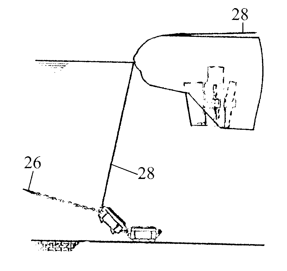
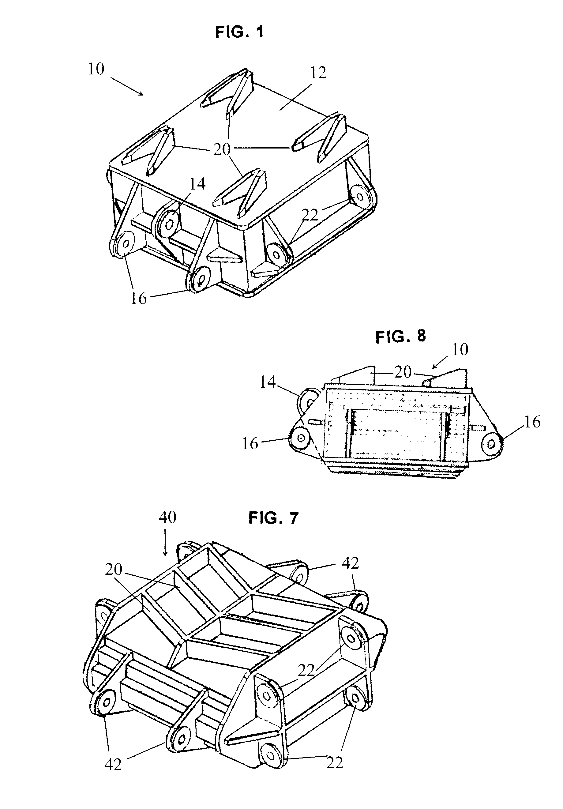
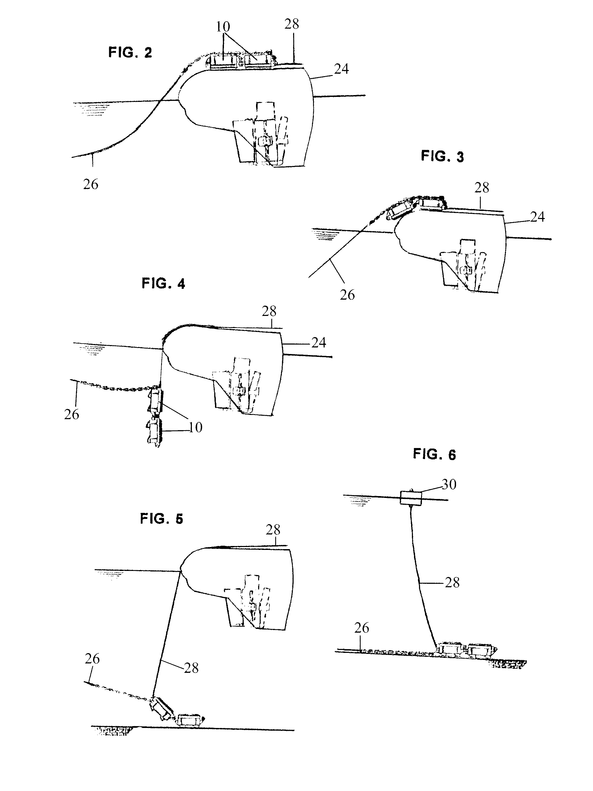
[0016]A single anchor unit 10 of the gravity anchor is illustrated in FIG. 1. The single unit will be referred to as the anchor unit for ease of reference. It should be understood that one or more anchor units 10 may be used in combination to provide the necessary weight and holding power in accordance with the requirements of each specific situation.

[0017]As seen in FIGS. 1 and 8, an anchor unit 10 has a top, a bottom, and four sides and is generally comprised of dead weight 12, main padeye 14, hinge padeyes 16, spikes 20, and handling padeyes 22.

[0018]Dead weight 12—The majority of the anchor unit's weight is present in the deadweight 12. It may be made completely of steel, a steel enclosure filled with lead weight, or a steel enclosure filled with concrete. Depending on the vessel, water depth, soil conditions, etc., each anchor unit 10 is envisioned to weigh in the range of 10 to 30 metric tons.

[0019]The main padeye 14 serves as the attachment point for the mooring line from the...


PUM


Abstract

A gravity anchor that includes one or more anchor units. The units are designed to be rotationally linked together so that multiple units can be used to provide the required weight. The units are designed for ease of handling on the vessel and to control the rotation of the units relative to each other to insure proper orientation on the seafloor. The units are designed to help them dig into the sea bed and enhance the drag and holding power

Description

FIELD AND BACKGROUND OF INVENTION[0001]The invention is related to anchors and more particularly to gravity anchors that are used to moor barges and vessels in place.[0002]Floating marine vessels and barges are subjected to external loads from the environment and from operation of the vessels. Environmental loads are mainly from waves, wind, and current. Operation loads originate from the function, such as towing, laying of submarine pipelines, etc. It is essential to hold the vessel at the desired designated station (station keeping) in order to execute the work offshore. “Station keeping” of the vessel is achieved by two methods—mooring by marine anchors and by dynamic positioning means such as thrusters.[0003]Mooring by marine anchors is typically the simplest way of station keeping a vessel. Various types of anchors have been used for this purpose. One type is the “gravity anchor” or the “deadweight anchor”.[0004]Anchor handling tug boats (AHT's) are the typical vessels / boats us...

Claims


Application Information

Patent Timeline
Patent Type & Authority Applications(United States)
IPC IPC(8): B63B21/24
CPCB63B21/29B63B21/243
Inventor PETERSEN, JIM B.JOE-JOE, CHELLAKAT SATYARAJ
Owner J RAY MCCDERMOTT SA
Why Eureka
Try Eureka