Unlock instant, AI-driven research and patent intelligence for your innovation.

Pneumatic tire

a technology of pneumatic tires and tires, applied in the field of pneumatic tires, can solve problems such as difficulty in meeting demand

Active Publication Date: 2011-04-28
YOKOHAMA RUBBER CO LTD
View PDF6 Cites 9 Cited by
  • Summary
  • Abstract
  • Description
  • Claims
  • Application Information

AI Technical Summary

Benefits of technology

[0013]According to the present disclosure, in a pneumatic tire having a designated tire inner side / outer side mounting orientation when mounted on a vehicle, by making the tan δ at 60° C. of the rubber composition forming the cap tread rubber layer on the vehicle outer side relatively greater, grip during cornering based on the physical properties of the cap tread rubber layer on the vehicle outer side can be enhanced and steering stability can be enhanced. On the other hand, by making the tan δ at 60° C. of the rubber composition forming the cap tread rubber layer on the vehicle inner side relatively less, heat generation in the cap tread rubber layer on the vehicle inner side can be suppressed. Therefore, variations in steering stability performance due to continued traveling can be suppressed while enhancing steering stability.
[0014]Furthermore, the under tread rubber layer is disposed in the tread portion as a base for the at least two types of cap tread rubber layers. By increasing the hardness at 20° C. of the rubber composition forming the under tread rubber layer and suppressing heat generation through lowering the tan δ at 60° C. of the rubber composition forming the under tread rubber layer, high-speed durability and steering stability during high-speed travelling can be further enhanced. Moreover, the under tread rubber layer can be added as a base to the cap tread rubber layers without negatively affecting riding comfort.
[0015]With the present disclosure, it is preferable that at least one main groove extending in a tire circumferential direction is provided in the tread portion, the at least one main groove forming an asymmetric tread pattern wherein a groove area ratio GAo of a ground contact region from a tread center-line to the vehicle outer side is less than a groove area ratio GAi of a ground contact region from the tread center-line to the vehicle inner side. As a result, the effect of suppressing variations in steering stability performance due to continued traveling can be sufficiently obtained while enhancing steering stability.
[0016]With the asymmetric tread pattern, it is preferable that a difference (GAi−GAo) between the groove area ratio GAo of the ground contact region of the vehicle outer side and the groove area ratio GAi of the ground contact region of the vehicle inner side is set to be in a range of from 1% to 15%. As a result, the effect of suppressing variations in steering stability performance due to continued traveling can be sufficiently obtained while enhancing steering stability.
[0019]Additionally, it is preferable that a height of the bead filler from a bead heel is 30% or less of a tire cross-section height, and a tan δ at 60° C. of a rubber composition forming the bead filler is 0.20 or less. By thus shortening the bead filler that repeatedly deforms during tire rolling and lowering the tan δ at 60° C. of the rubber composition forming the bead filler, heat generated in the tire due to continued traveling on a circuit can be suppressed and variations in steering stability performance can be suppressed. As a result, initial steering stability can be maintained over extended periods of time during continued driving.
[0021]While applicable to all types of pneumatic tires, significant effects can be obtained when the present disclosure is applied to pneumatic tires having tire sizes with aspect ratios of 50% or less, which have narrow flex zones. Particularly, significant effects can be obtained when applied to pneumatic tires to be mounted on vehicles that have camber angles of from −0.5° to −4.0°.

Problems solved by technology

However, with pneumatic tires to be mounted on vehicles for which high-speed travelling is expected, there is a demand for further enhancement of steering stability and high-speed durability during high-speed travelling, and that demand is difficult to meet.

Method used


Image

  • Pneumatic tire
  • Pneumatic tire
  • Pneumatic tire

Examples


working examples

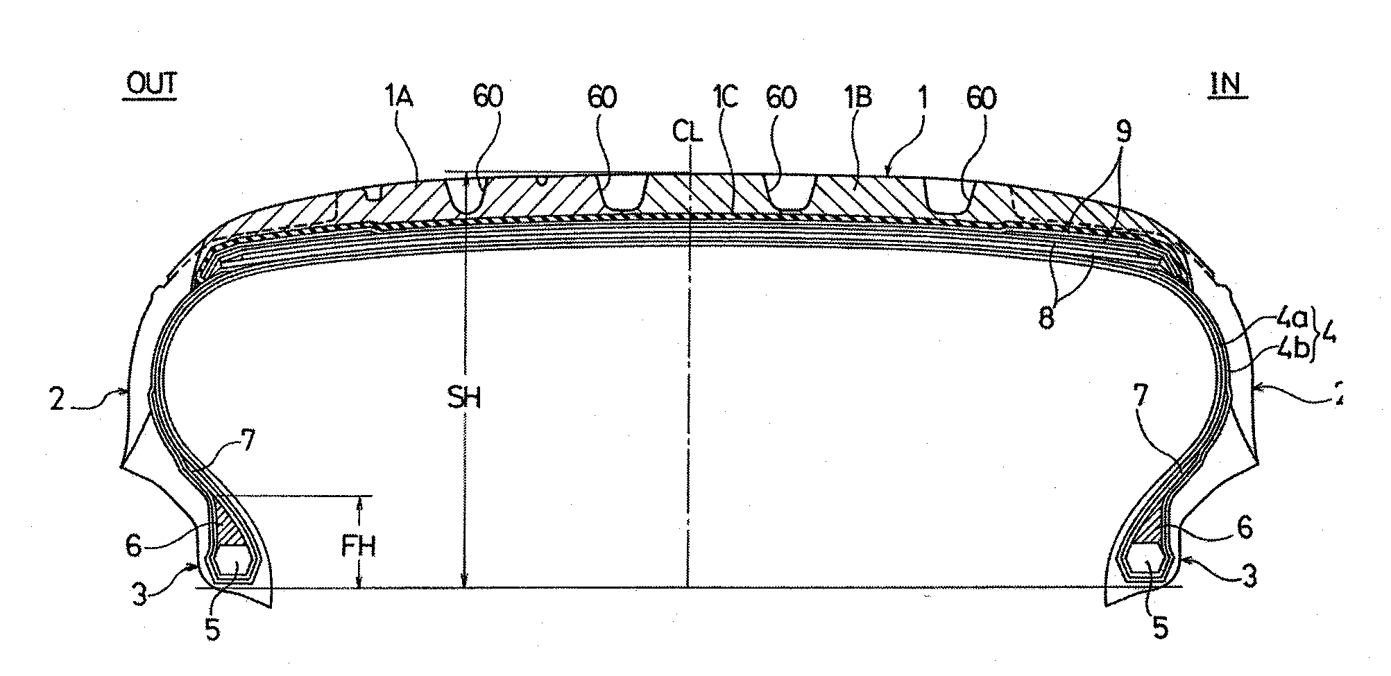
[0045]Pneumatic tires for a Conventional Example, Working Examples 1 to 5, and Comparative Examples 1 to 4 were manufactured having a tire size of 235 / 40 R18. Each pneumatic tire included a carcass layer with a single-ply construction mounted, having a cord angle with respect to the tire circumferential direction of 85°, between a pair of bead portions; and a belt layer disposed on an outer circumferential side of the carcass layer corresponding to the tread portion, wherein the carcass layer is wrapped around bead core disposed in each of the bead portions from a tire inner side to a tire outer side, a bead filler disposed on the bead cores is sandwiched between a main body portion and a wrapped portion of the carcass layer, and the wrapped portion of the carcass layer is extended to a lower region of the belt layer so as to overlap with an end of the belt layer. In such pneumatic tires the height of the bead filler from the bead heel (percentage of the tire cross-section height), ...


PUM


Abstract

A pneumatic tire includes at least two types of cap tread rubber layers made from differing rubber compositions disposed in a tread portion. A tan δ at 60° C. of a rubber composition forming the cap tread rubber layer on a vehicle outer side is greater than a tan δ at 60° C. of a rubber composition forming the cap tread rubber layer on a vehicle inner side. A ratio (tan δH / tan δL) of a maximum tan δH to a minimum tan δL at 60° C. of the tan δ of the rubber compositions forming the at least two types of cap tread rubber layers is from 1.05 to 1.80. An under tread rubber layer disposed in the tread portion has an average thickness from 0.8 mm to 4.0 mm. A hardness of a rubber composition forming the under tread rubber layer is from 73 to 83. A tan δ at 60° C. of the rubber composition forming the under tread rubber layer is 0.25 or less.

Description

PRIORITY CLAIM[0001]This application is based upon and claims the benefit of priority from Japanese Patent Application No. 2009-247978, filed Oct. 28, 2009, the entire contents of which is incorporated herein by reference.BACKGROUND[0002]1. Technical Field[0003]The present disclosure relates to a pneumatic tire having a designated tire inner side / outer side mounting orientation when mounted on a vehicle and particularly relates to a pneumatic tire that can enhance steering stability and high-speed durability during high-speed travelling without negatively affecting riding comfort.[0004]2. Related Art[0005]In recent years, there have been strict demands for reductions in the weight of pneumatic tires that are to be mounted on vehicles for which high-speed travelling is expected, such as sports cars and the like. However, for pneumatic tires that satisfy the demand for reduced weight, there is an additional demand of ensuring steering stability equivalent to or greater than that of co...

Claims


Application Information

Patent Timeline
Patent Type & Authority Applications(United States)
IPC IPC(8): B60C11/00
CPCB60C11/00B60C11/0302B60C15/0045B60C11/033Y10T152/10846B60C2011/0025B60C2011/0033B60C11/005Y10T152/10837B60C11/0066
Inventor DAISHO, YASUJIROU
Owner YOKOHAMA RUBBER CO LTD