
Electric drive system for passive vehicle

Inactive Publication Date: 2011-04-28
ARES TRANSPORTATION TECH
View PDF27 Cites 139 Cited by
  • Summary
  • Abstract
  • Description
  • Claims
  • Application Information

AI Technical Summary

Benefits of technology

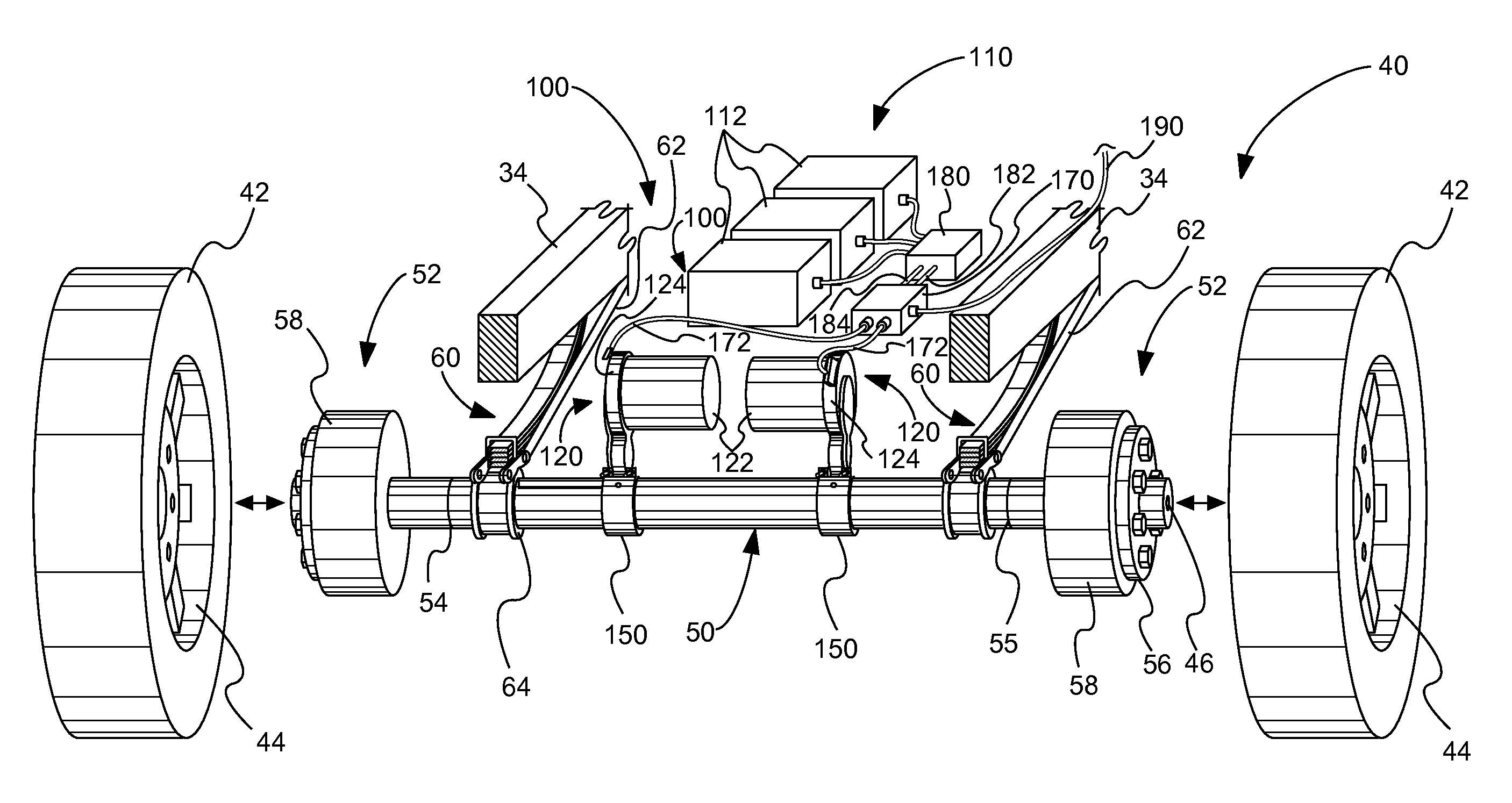
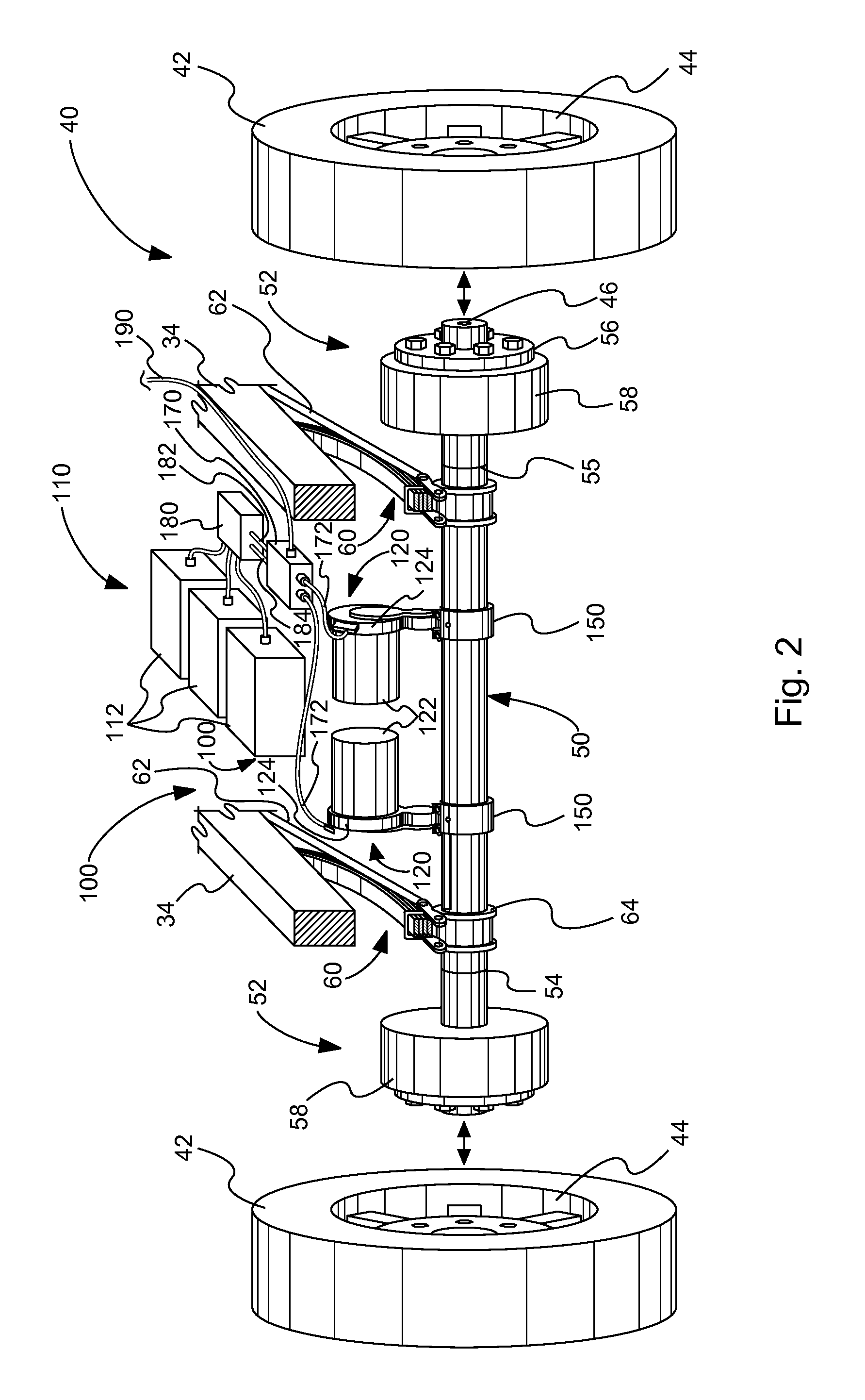
[0007]The subject matter of the present application has been developed in response to the present state of the art, and in particular, in response to the problems and needs in the art that have not yet been fully solved by currently available electric drives for passive axles of passive vehicles. Accordingly, the subject matter of the present application has been developed to provide an apparatus, system, and method that overcomes most of the shortcomings of the prior art. For example, in one embodiment described in the present disclosure, an electronic drive system includes two electric motors each independently driving a separate wheel. The electronic drive system can be coupled directly to a vehicle's passive hollow structural axle to independently drive respective splined drive axles positioned within the hollow structural axle without the need for an intermediate differential gear box. The electronic drive system can be inexpensive, compact, and light-weight, and does not degrade the structural integrity of the trailer's passive axle design.
[0008]Further, the electronic drive system can be configured to be easily retrofitted onto existing passive vehicles.
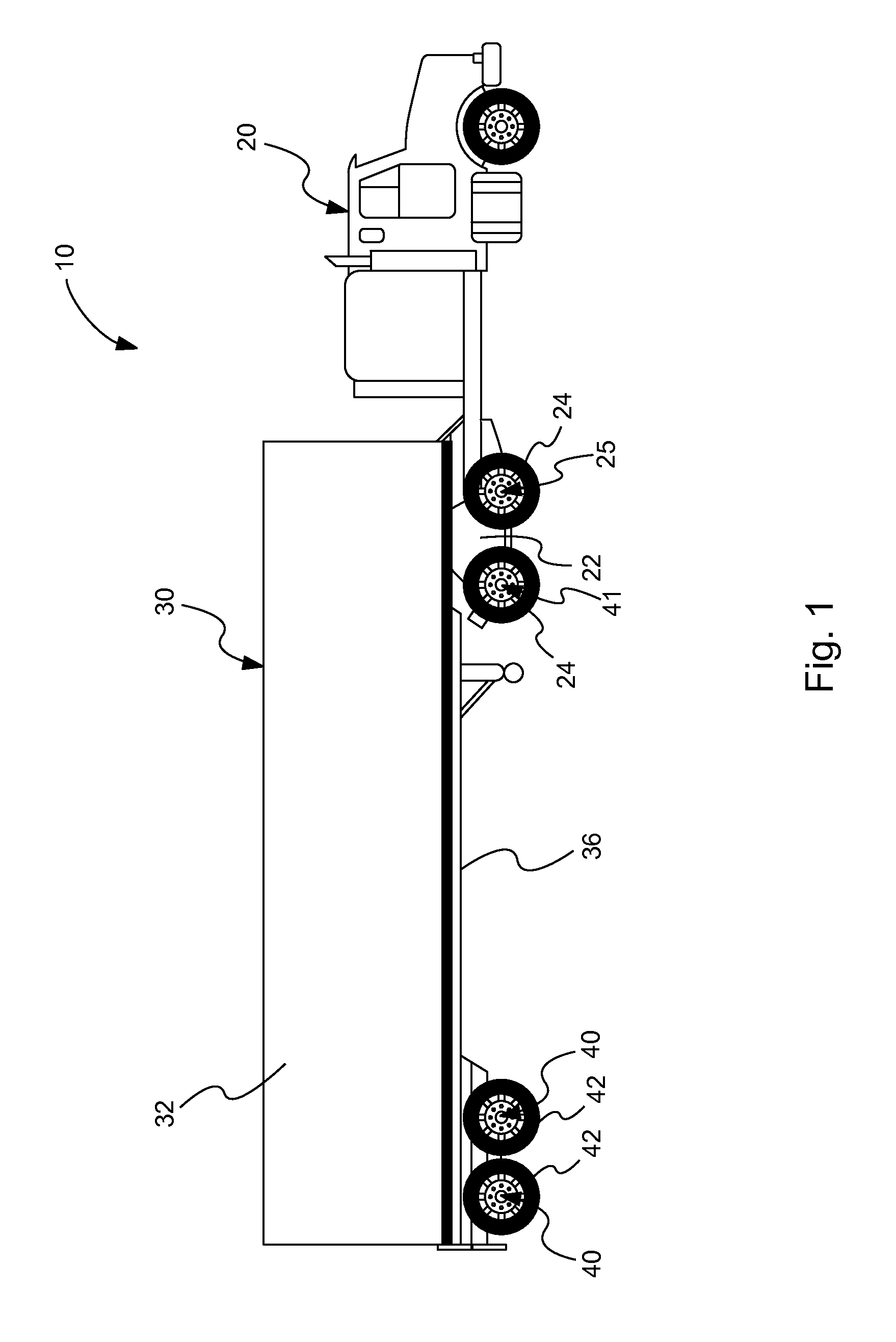
[0010]Moreover, for passive vehicles with adjacent passive axles and drive axles, the electric drive system can be utilized to restore mobility to an immobilized passive vehicle with its passive axle tires in contact with a travel surface and drive axle tires suspended above the travel surface. More specifically, the electric drive system can be operated to move the vehicle using the passive axle tires in contact with the travel surface such that contact between the drive axle tires and the travel surface is restored.

Problems solved by technology

However, such passive axle drive systems suffer from several drawbacks.
Due to the large size and robust configuration of differential gear boxes, these passive axle drive systems tend to be expensive, complex, and heavy.
Yet other passive axle drive systems cannot be easily retrofitted onto existing trailers.
Many conventional passive axle drive systems are not self-sustaining.
In other words, many systems do not include regenerative braking capability.
For this reason, trailers equipped with conventional passive axle drive systems do not function independently of the tractor and are not interchangeable with different tractor makes and models.
Further, some passive semi-tractors with one or more passive axles adjacent a drive axle may become immobile under certain driving conditions.
Because the tires of the drive axle are out of contact with the road surface, the semi-tractor is effectively stranded or immobilized.

Method used


Image

  • Electric drive system for passive vehicle
  • Electric drive system for passive vehicle
  • Electric drive system for passive vehicle

Examples


Embodiment Construction

[0035]Reference throughout this specification to “one embodiment,”“an embodiment,” or similar language means that a particular feature, structure, or characteristic described in connection with the embodiment is included in at least one embodiment of the present disclosure. Appearances of the phrases “in one embodiment,”“in an embodiment,” and similar language throughout this specification may, but do not necessarily, all refer to the same embodiment. Similarly, the use of the term “implementation” means an implementation having a particular feature, structure, or characteristic described in connection with one or more embodiments of the present disclosure, however, absent an express correlation to indicate otherwise, an implementation may be associated with one or more embodiments.

[0036]In the following description, numerous specific details are provided to impart a thorough understanding of embodiments of the present disclosure. One skilled in the relevant art will recognize, howe...


PUM

PropertyMeasurementUnit
Poweraaaaaaaaaa

Abstract

One embodiment of an electric drive system includes first and second gear assemblies coupled to a hollow axle tube, and first and second electric motors respectively coupled to the first and second gear assemblies. Further, the electric drive system includes first and second drive axles positioned within the hollow axle tube. The first drive axle includes a first end portion coupled to a first wheel and a second end portion coupled to the first gear assembly. Similarly, the second drive axle includes a first end portion coupled to a second wheel spaced-apart from the first wheel and a second end portion coupled to the second gear assembly. Actuation of the first electric motor rotates the first drive axle and first wheel via the first gear assembly and actuation of the second electric motor rotates the second drive axle and second wheel via the second gear assembly.

Description

CROSS-REFERENCE TO RELATED APPLICATION[0001]This application claims the benefit of U.S. Provisional Patent Application No. 61 / 254,948, filed Oct. 26, 2009, which is incorporated herein by reference.FIELD[0002]The present disclosure is related generally to a vehicle propulsion system, and more specifically to an electric drive system for a passive vehicle.BACKGROUND[0003]Many conventional wheeled vehicles are passive. As defined herein, a passive vehicle is a vehicle that includes only passive or non-driven axles or at least one passive or non-driven axle. One example of a passive vehicle is the trailer portion of a tractor-trailer vehicle used for the transportation of goods. The tractor portion of a tractor-trailer vehicle also can be a passive vehicle where the tractor portion includes a drive axle and a dead or passive axle (e.g., a tag axle positioned rearward of the drive axle and a pusher axle positioned forward of the drive axle). Conventional tractor-trailer vehicles include...

Claims


Application Information

Patent Timeline
IPC IPC(8): B60K1/02B23P17/00
CPCB60K1/04B60K7/0007B60K17/36B60K2001/0444B60K2007/0046B60K2007/0061Y10T29/49716B60Y2200/147B60L11/005B60L2260/28Y02T10/7022Y02T10/648B60L2220/46B60L50/40Y02T10/70Y02T10/64
Inventor PRUITT, STEVERIX, ALDEN
Owner ARES TRANSPORTATION TECH
Learn More