
Display channel apparatus

a channel apparatus and display technology, applied in the field of display channel apparatus, can solve the problems of difficult and/or cumbersome manual assembly, expensive subcomponents, and high cost of tooling, and achieve the effects of low cost of parts and labor, convenient dense packaging, and flexible assembly

Inactive Publication Date: 2011-04-28
SEABROOK PLASTICS
View PDF35 Cites 52 Cited by
  • Summary
  • Abstract
  • Description
  • Claims
  • Application Information

AI Technical Summary

Benefits of technology

[0016]In a narrower aspect of the present invention, the channel-forming components can be interfit prior to being assembled together to form a multi-channel apparatus and to increase a ship density by at least 70%.
[0023]An object of the present invention is to provide a display channel apparatus that can be assembled in a side-ways horizontal direction to form a multi-channel display apparatus, the components providing flexibility of assembly, low cost of parts and labor, and use of communized basic individual components that facilitate dense packaging for storage, transport, and shipping (prior to or after partial assembly or full assembly).

Problems solved by technology

Presently known display channel apparatus include expensive subcomponents, expensive tooling required to form the same, and difficult and / or cumbersome manual assembly.
Further, the components and related assemblies have a poor storage and shipping density, are cumbersome to handle and ship, and are often overly complex and not intuitive to assemble.
Further known apparatus waste shelf space, are inflexible to use, and are often difficult or impossible to fix, refurbish, or recycle.

Method used


Image

  • Display channel apparatus
  • Display channel apparatus
  • Display channel apparatus

Examples


Embodiment Construction

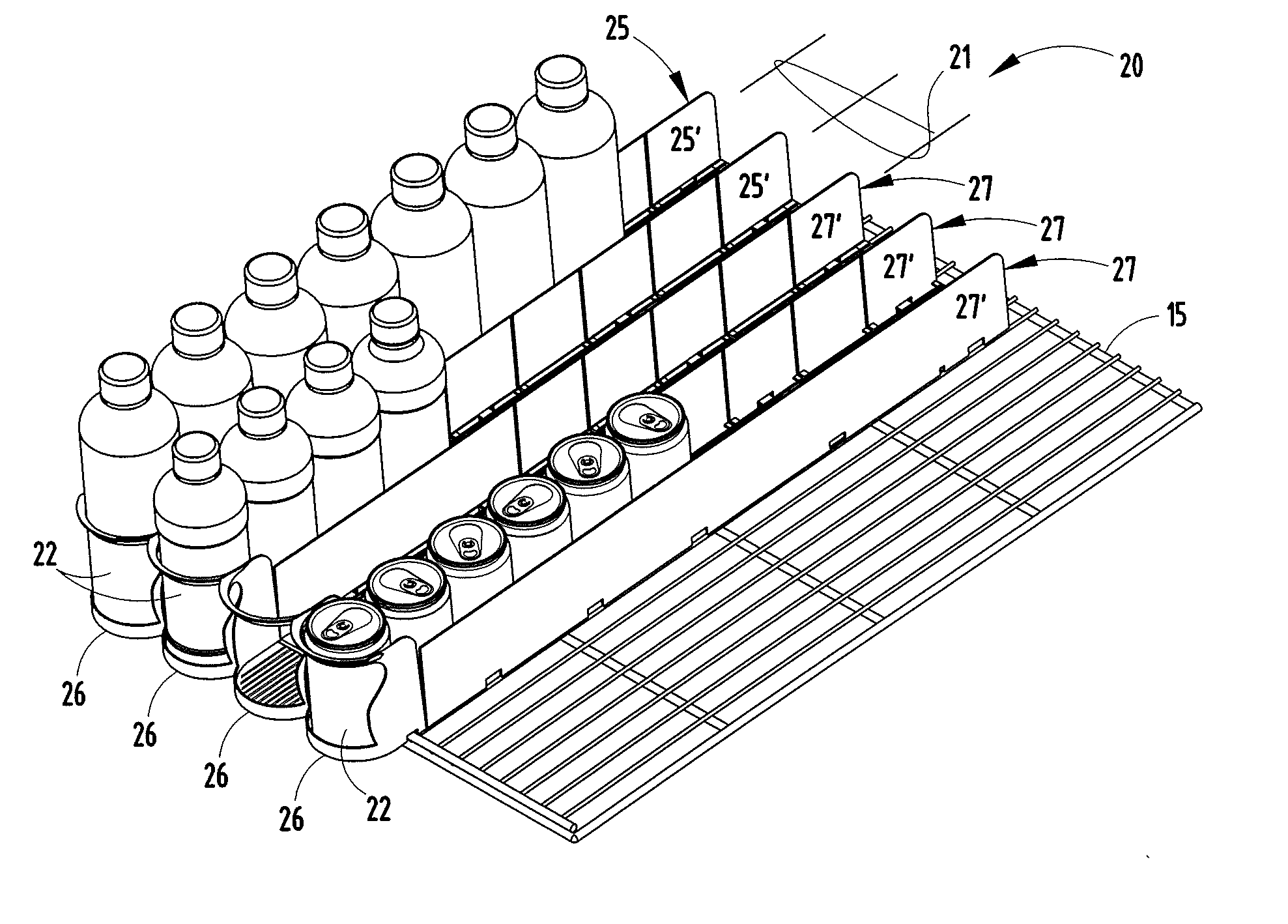
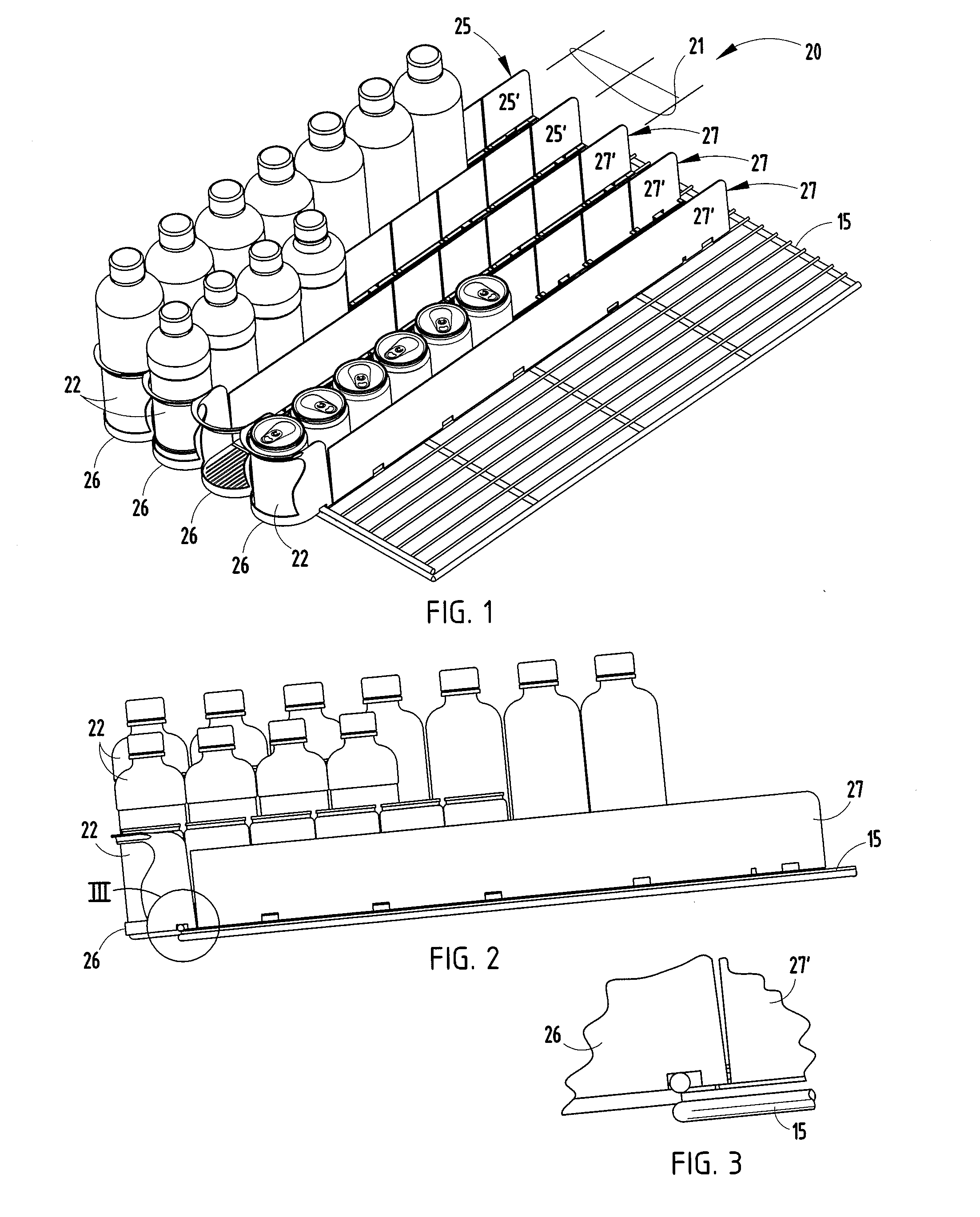
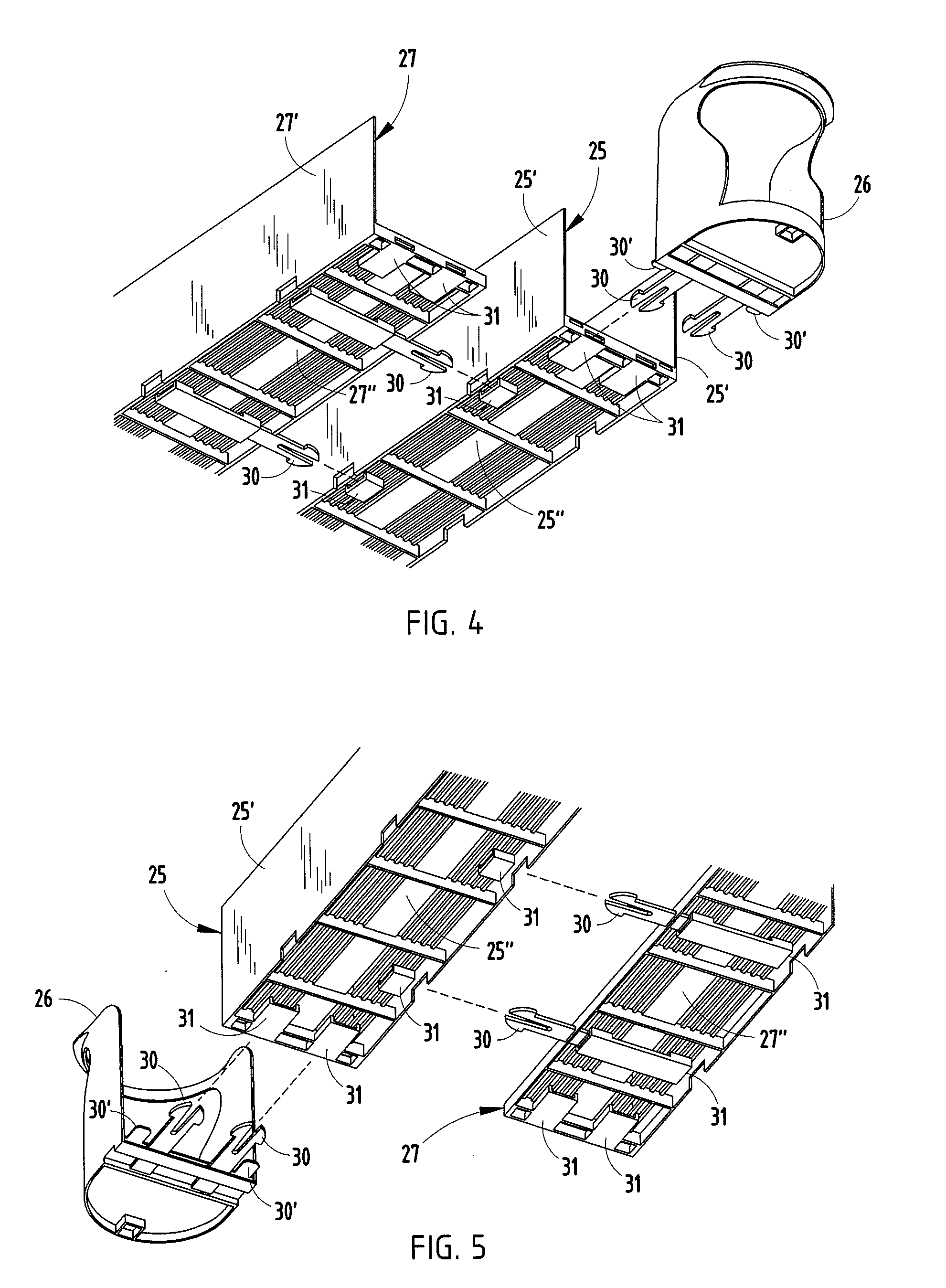
[0058]The present display channel apparatus 20 (FIG. 1) for shelves 15 of a commercial refrigeration unit (see unit 14A in FIG. 21) provides multiple parallel channels / paths 21 for containers 22 to slide forward, thus allowing singular selection from a front of the apparatus 20. The illustrated apparatus 20 (FIG. 1) is made of polymeric components configured to horizontally snap assemble, and in particular includes a U-shaped channel component 25 (also called “starter channels”) forming a first path 21 for the containers, a front component 26 (also called “front”) attached to the channel 25 for providing a front stop where a container can be selected from a front of the path 21. A plurality of L-shaped channel components 27 (also called “extender channels”) are attached to sides of the U-shaped channel 25, each including a front 26, and are attached to each other to form additional paths extending parallel and adjacent the first path. A rear component 28 is also attached to define a...


PUM

PropertyMeasurementUnit
Fractionaaaaaaaaaa
Fractionaaaaaaaaaa
Lengthaaaaaaaaaa

Abstract

A display channel apparatus for displaying containers comprises a starter channel, a plurality of extender channels, fronts and rears. These components include a plurality of horizontally-engaging mating connectors that are preferably integrally formed, and formed without slides or pulls in the plastic molding dies, and further that have sufficient length and stiffness to provide a stable assembly after interconnection. They also facilitate quick assembly by sliding engagement on a table top. In one form, the components are laterally compressible / extendable to a selected width for receiving a particular sized product, and clips or connectors are adapted to fix the selected width. The individual components and the assembled components mate together for densely-stacked compact arrangements for storage (unassembled or assembled) and / or shipping. Also, the components can be selectively assembled to meet individual needs and preferences, as well as broken down for reuse, refurbishing, and / or recycling.

Description

[0001]This claims benefit under 35 U.S.C. §119(e) of provisional application Ser. No. 61 / 254 / 381, filed Oct. 23, 2009, entitled DISPLAY CHANNEL APPARATUS, the entire contents of which are incorporated herein in their entirety.BACKGROUND[0002]The present invention relates to a display channel apparatus which can be readily assembled to form a multi-channel display rack, and more particularly to such a display rack apparatus having an unusual configuration, including flexibility of assembly, low cost, and communized basic individual components that facilitate dense packaging for storage, transport, and shipping (before assembly, after partial assembly and / or after full assembly).[0003]Presently known display channel apparatus include expensive subcomponents, expensive tooling required to form the same, and difficult and / or cumbersome manual assembly. Further, the components and related assemblies have a poor storage and shipping density, are cumbersome to handle and ship, and are ofte...

Claims


Application Information

Patent Timeline
IPC IPC(8): A47F7/00B23P11/00
CPCY10T29/49945A47F5/005
Inventor COUSIN, SERGE L.CLAEYS, ROBERT A.
Owner SEABROOK PLASTICS
Learn More