Display apparatus

a display apparatus and display technology, applied in the field of display apparatuses, can solve the problems of affecting optical performance, reducing the reliability of the display apparatus, and beginning to use the display apparatus in more severe environmental conditions, so as to improve workability and reliability of connections, simplify the connection structure, and make the display apparatus more thin

Inactive Publication Date: 2011-04-28
SHARP KK
View PDF23 Cites 32 Cited by
  • Summary
  • Abstract
  • Description
  • Claims
  • Application Information

AI Technical Summary

Benefits of technology

[0018]The present invention has been made in view of the above circumstance as described above, and it is an object thereof to provide a display apparatus in which luminous intensity when the display apparatus is viewed from the front is improved, and in which it is possible to perform display while clearly distinguishing between lit and non-lit portions, and also, the connection structure is simplified so that workability and reliability of connections are improved, and the display apparatus can be made more thin.

Problems solved by technology

However, display apparatuses have begun to be used in more severe environmental conditions due to expanded fields of use.
In such a case, due to heat stress the constituent members that constitute the display apparatus repeatedly expand and contract, so structural integrity changes over time and weakens, adversely affecting optical performance.
In addition, soldered portions where built-in electrical components such as drive circuits, wires and so forth are electrically connected deteriorate, so that disconnections or the like occur, and thus reliability of the display apparatus may sometimes be reduced.
However, because the pins 121 that electrically connect the light-emitting device mounting substrate 120d to the drive substrate 120c are necessary, and the wiring path also is long, there is a risk that workability of the wiring and reliability will decrease.
Therefore, luminous intensity is not sufficient when viewing the display apparatus 101 from the front, so although the display apparatus 101 can be used as an indoor display apparatus for indoors use, it cannot be used as an outdoor display apparatus.
In a display apparatus in which molded-type light-emitting devices are adopted, a lead of the molded-type light-emitting devices is led out on the back side of the light-emitting device wiring substrate where the light-emitting devices are mounted, so it is not possible to dispose a drive circuit on the back face of the light-emitting device wiring substrate.
Therefore, it is necessary to connect the light-emitting device wiring substrate and the drive circuit wiring substrate, and because the number of wires necessary for connection corresponds to the number of molded-type light-emitting devices, particularly in the case of application to a large-screen display apparatus, there is a risk that there will be a great number of wires, and as a result the workability of connections, and reliability, will decrease.
Also, soldering is used to implement the wiring between the light-emitting device wiring substrate and the drive circuit wiring substrate, and this soldering takes time and labor, resulting in increased production cost.
Furthermore, because there are soldering connections in many places, there is an increase in defects such as disconnections, and so there is a risk of reducing connection workability and reliability.
Due to applying a large pulse current, the forward voltage of the light-emitting devices increases, so power consumption increases, and thus power consumption of the display apparatus is increased, and reliability is reduced.

Method used


Image

  • Display apparatus
  • Display apparatus
  • Display apparatus

Examples


Embodiment Construction

[0078]Hereinafter, an embodiment(s) of the present invention will be described based on the accompanying drawings.

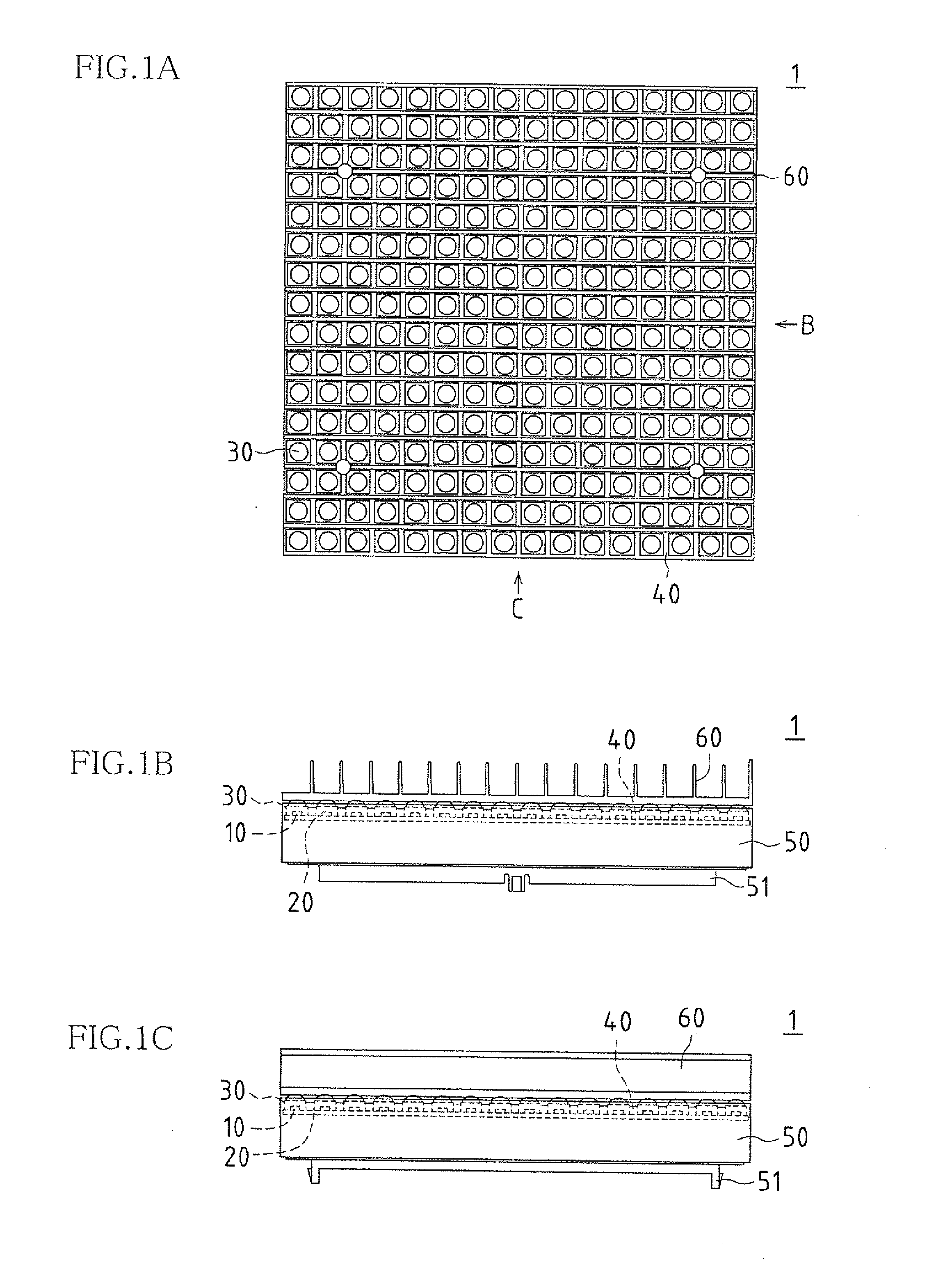
[0079]FIGS. 1A to 1C illustrate a display apparatus according to an embodiment of the present invention, where FIG. 1A is a plan view, FIG. 1B is a side view viewed from the direction of arrow B in FIG. 1A, and FIG. 1C is a side view viewed from the direction of arrow C in FIG. 1A.

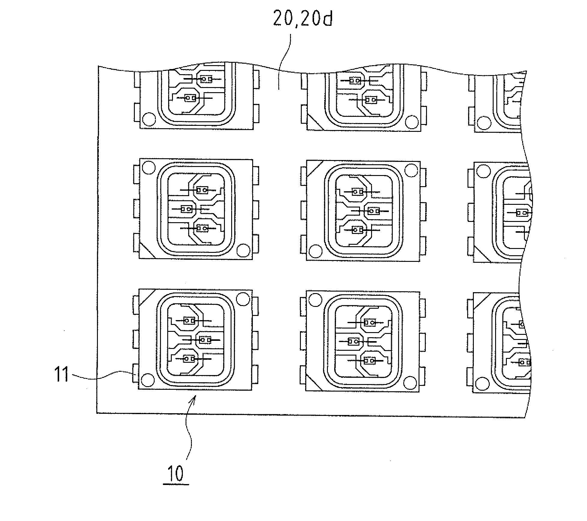
[0080]The display apparatus 1 according to the present embodiment is provided with surface mount-type light-emitting devices 10 that are surface mount-type light-emitting devices, a wiring substrate 20 where the surface mount-type light-emitting devices 10 have been mounted, lens units 30 that have been disposed in front of the surface mount-type light-emitting devices 10, and a frame body portion 40 disposed surrounding the circumference of the lens unit 30. The wiring substrate 20 is attached to a case 50, and visor portions 60 are disposed on the front side of the lens units 30. The case 50 ...


PUM


Abstract

A display apparatus according to one embodiment of the present invention is a display apparatus comprising a surface mount-type light-emitting device having an external terminal for surface mounting; a wiring substrate where the surface mount-type light-emitting device has been mounted; a lens unit disposed opposing the surface mount-type light-emitting device; and a frame body portion disposed surrounding the lens unit.

Description

CROSS-REFERENCE TO RELATED APPLICATIONS[0001]This application claims priority under 35 U.S.C. §119(a) on Patent Application No. 2009-243588 filed in Japan on Oct. 22, 2009, the entire contents of which are herein incorporated by reference.BACKGROUND OF THE INVENTION[0002]1. Field of the Invention[0003]The present invention relates to a display apparatus provided with a wiring substrate on which a surface mount-type light-emitting device has been disposed.[0004]2. Description of the Related Art[0005]Conventionally, display apparatuses are known in which a large screen is configured by mounting a plurality of light-emitting devices (light-emitting diodes: LEDs) on a wiring substrate. The light-emitting devices are capable of self-emission of the three primary colors of light (red: R, green: G, and B: blue), and therefore are adopted in display apparatuses in many fields.[0006]However, display apparatuses have begun to be used in more severe environmental conditions due to expanded fie...

Claims


Application Information

Patent Timeline
Patent Type & Authority Applications(United States)
IPC IPC(8): G09G5/00H01L33/08
CPCG09F9/33H01L2224/48247H01L33/58H01L25/0753
Inventor ITO, MASAYUKIHATA, TOSHIOTAKASUGI, KEIJI
Owner SHARP KK
Why Eureka
Try Eureka