Heterodyne interferometer

a technology of interferometer and heterodyne, which is applied in the field of heterodyne interferometer, can solve the problems of insufficient resolution and precision of the above-michelson interferometer, increased heat generation of the circuit, and difficulty in circuit design of the counter and the signal processor, so as to achieve the effect of improving measurement resolution

Inactive Publication Date: 2011-04-28
CANON KK
View PDF16 Cites 36 Cited by
  • Summary
  • Abstract
  • Description
  • Claims
  • Application Information

AI Technical Summary

Benefits of technology

[0013]The present invention provides a heterodyne interferometer that has an advantage in terms of measurement resolution.

Problems solved by technology

However, the above Michelson interferometer has an insufficiently low resolution and precision because the counting unit (resolution) in the phase meter / accumulator is as low as the frequency of a sine periodical signal.
Nevertheless, since the frequency counted in the counter (phase meter / accumulator) is multiplied N times and thus too high, circuit designs of the counter and the signal processor may become difficult, a complex signal processing algorithm may be required, or a amount of heat generated from the circuit may increase.
Nevertheless, it is generally difficult to process high frequency heterodyne signals.

Method used


Image

  • Heterodyne interferometer
  • Heterodyne interferometer
  • Heterodyne interferometer

Examples


first embodiment

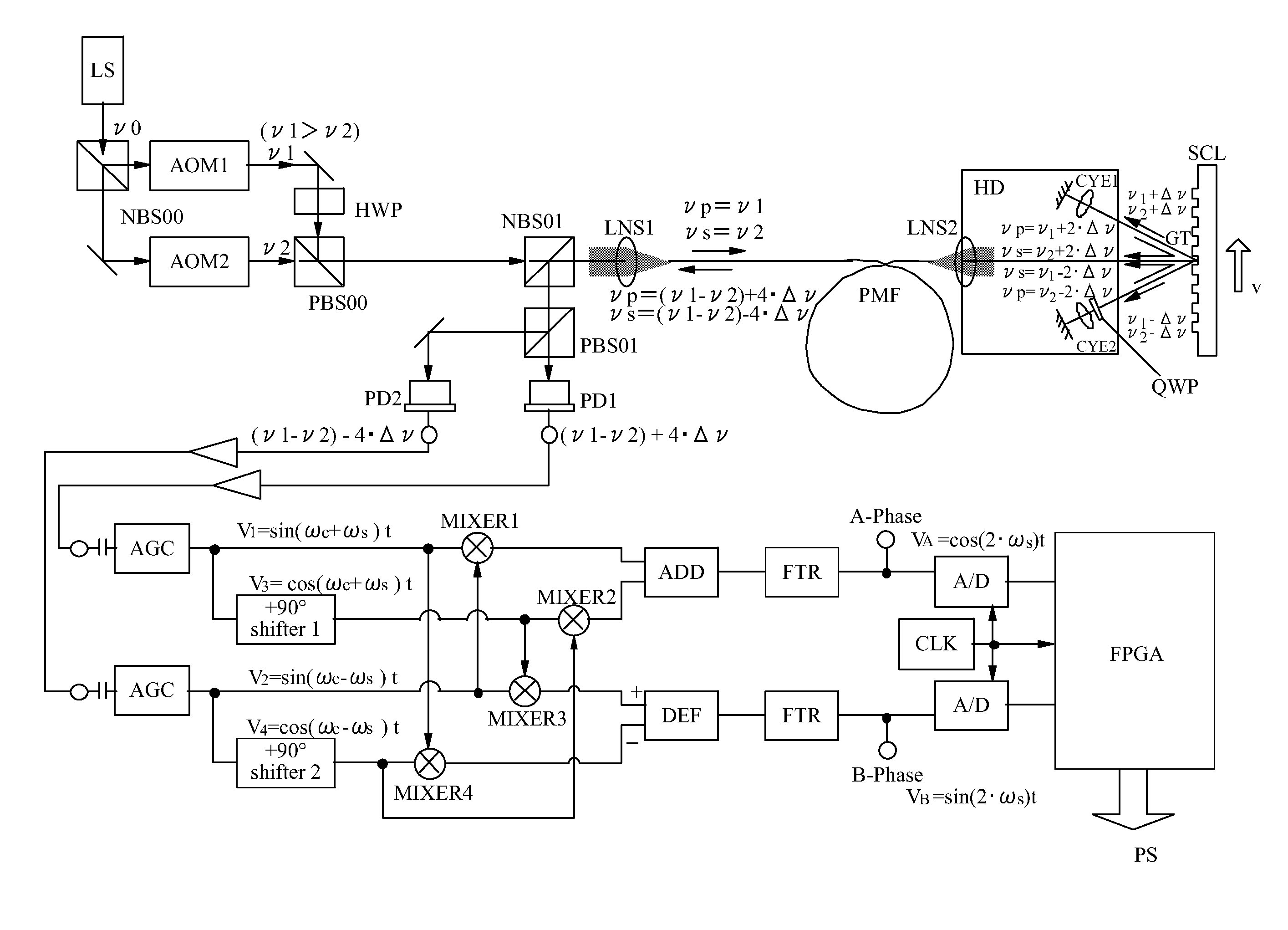
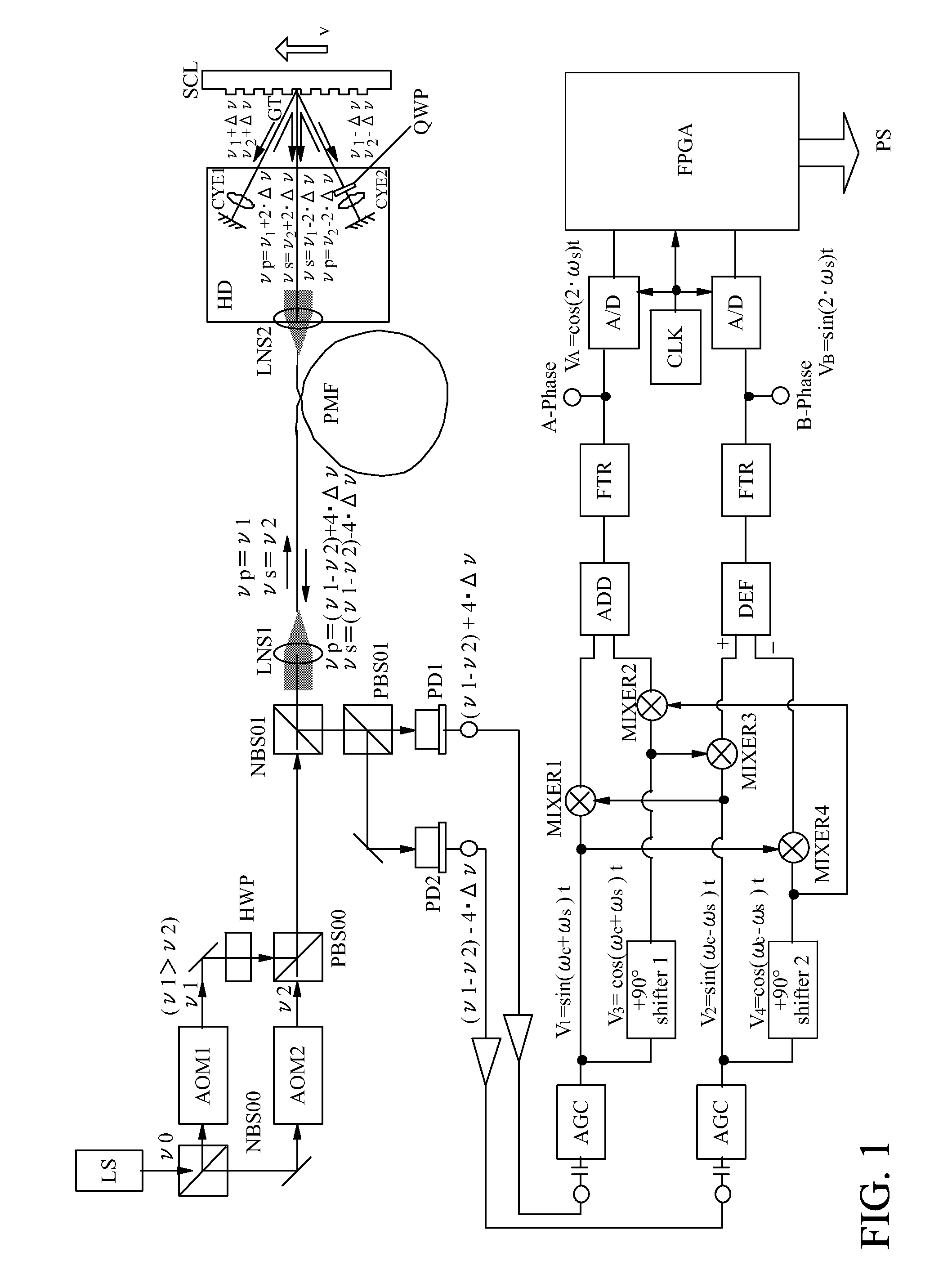
[0022]FIG. 1 illustrates an interferometer encoder including a diffraction grating as a heterodyne interferometer according to a first embodiment of the present invention.

[0023]A parallel light flux (with a frequency of ν0) that is linearly polarized light emitted in a 0° azimuth emitted from a laser light source LS is split into two by a beam splitter NBS00. A reflection light flux from the beam splitter NBS00 is converted into a light flux having a frequency of ν1=ν0+320 MHz by an acousto-optical element AOM1, and a transmission light flux through the beam splitter NBS00 is converted into a light flux having a frequency of ν2=ν0+300 MHz by an acousto-optical element AOM2. “ν0” is an (original) frequency of the laser light source LS and, for example, is ν0=299792458 / 850×10−9=352.6 THz for a laser light source of 850 nm.

[0024]A polarization plane of one of these two light fluxes is rotated by 90° by a half waveplate HWP, and these two light fluxes are synthesized with each other in ...

second embodiment

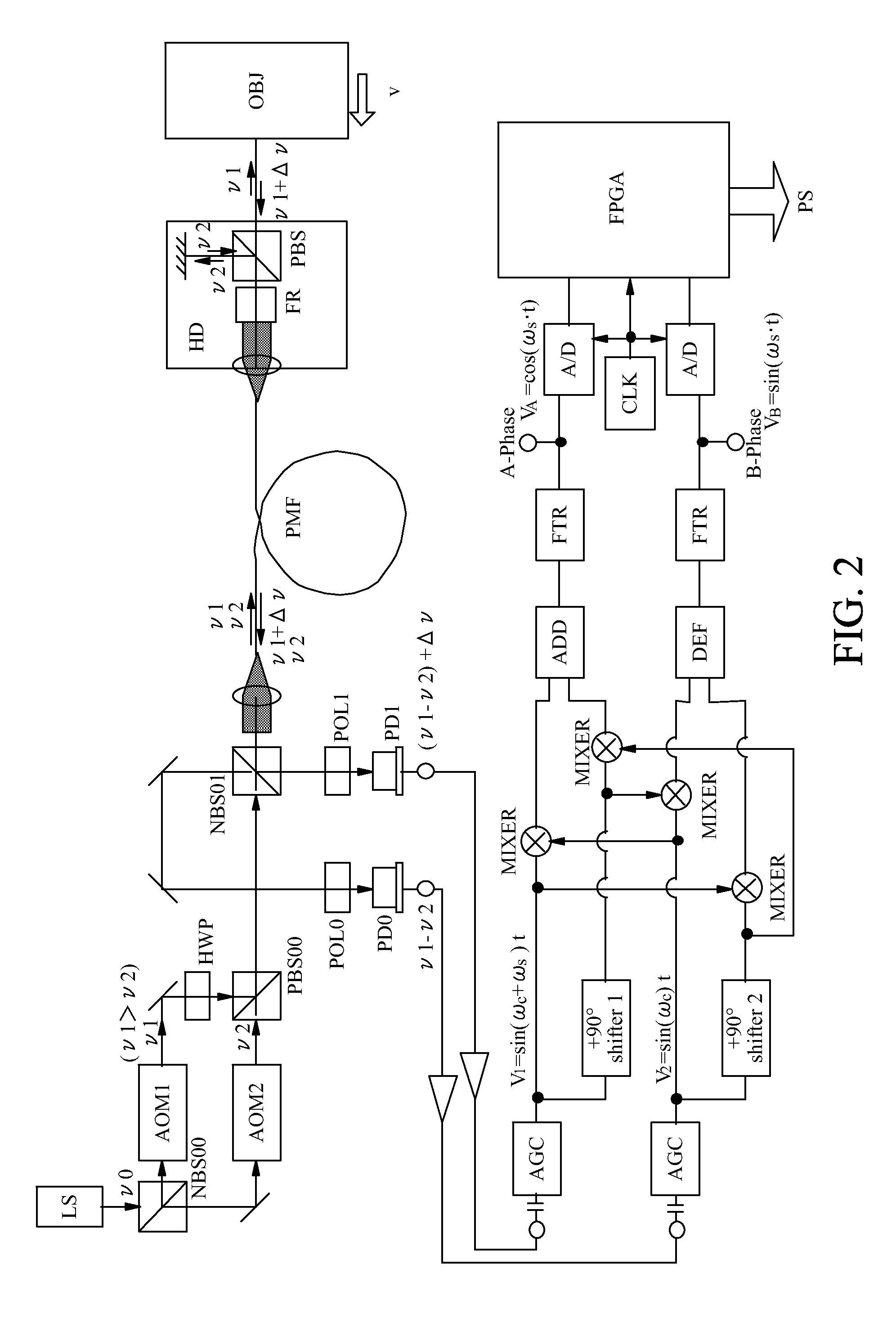
[0050]FIG. 2 illustrates a Michelson interferometer as a heterodyne interferometer according to a second embodiment of the present invention.

[0051]A part of the light flux emitted from the two-frequency light source including a laser light source LS, an acousto-optical elements AOM1 and AOM2 similar to the first embodiment is reflected on the non-polarization beam splitter NBS01 and extracted. The extracted light flux (second light) enters the signal generator, and is photoelectrically converted (detected) by a (second) light-receiving element PD0 via a polarizing plate POL0 of a 45° azimuth. This light flux and an output signal (reference frequency signal) from the light-receiving element PD0 have the same reference frequency as a frequency difference (ν1−ν2) of the two-frequency light source.

[0052]On the other hand, the light flux that has transmitted through the non-polarization beam splitter NBS01 enters a Faraday element FR in a detection head HD (irradiator) via a polarization...

third embodiment

[0063]FIG. 3 illustrates a structure of a signal generator in a heterodyne interferometer according to a third embodiment of the present invention. This signal generator is an illustrative improvement configured to reduce an error of the phase shifter for the signal generator of the first and second embodiments.

[0064]Usually, a 90° phase shifter that uses an analog circuit causes a phase error as a frequency of an input signal varies, and thus a final sine signal is likely to contain a frequency component that is twice as high as the heterodyne frequency.

[0065]Accordingly, this embodiment generates a phase shifted signal by shifting a signal having an original phase of 0° at phase shifters (shifter1 and shifter2) by θ≈90°, and generates a signal by adding the signal having the phase of 0° to the phase shifted signal, and a signal by subtracting the signal having the phase of 0° from the phase shifted signal. Since the post-addition signal and the post-subtraction signal have a phase...


PUM


Abstract

A heterodyne interferometer includes a light source, an optical system, and a signal generator including at least two light-receiving elements that respectively output a first signal and a second signal. The signal generator generates a third signal and a fourth signal of which phases are respectively shifted by 90° from phases of the first signal and the second signal, generates a first periodic signal by adding a signal that is obtained by multiplying the first signal and the second signal to a signal that is obtained by multiplying the third signal and the fourth signal, and generates a second periodic signal by subtracting a signal that is obtained by multiplying the first signal and the fourth signal from a signal that is obtained by multiplying the second signal and the third signal.

Description

BACKGROUND OF THE INVENTION[0001]1. Field of the Invention[0002]The present invention relates to a heterodyne interferometer.[0003]2. Description of the Related Art[0004]A heterodyne method of a light-interference measurement apparatus (“heterodyne interferometer”) is used as an apparatus configured to measure a physical amount such as an object's displacement amount and moving velocity, with a resolution (resolving power) of a submicron order (see Japanese Patent No. 2,845,700).[0005]A typical example of the heterodyne interferometer is a Michelson (length-measuring) interferometer configured to count a difference between a frequency-modulated signal (heterodyne signal) and a reference frequency signal. This apparatus converts a light flux from a laser light source into two light fluxes having frequencies and polarization azimuths that are different from each other (referred to as “two-frequency light fluxes” hereinafter) utilizing an acousto-optical element, and synthesizes these ...

Claims


Application Information

Patent Timeline
Patent Type & Authority Applications(United States)
IPC IPC(8): G01B9/02
CPCG01B9/02002G01B9/02018G01B2290/30G01B2290/70G01B2290/15G01B9/02065G01P3/36G01B9/02003
Inventor ISHIZUKA, KO
Owner CANON KK
Why Eureka
Try Eureka