Method and device for spectral analysis of an echographic signal
- Summary
- Abstract
- Description
- Claims
- Application Information
AI Technical Summary
Benefits of technology
Problems solved by technology
Method used
Image
Examples
Embodiment Construction
[0084]General Description of the Apparatus
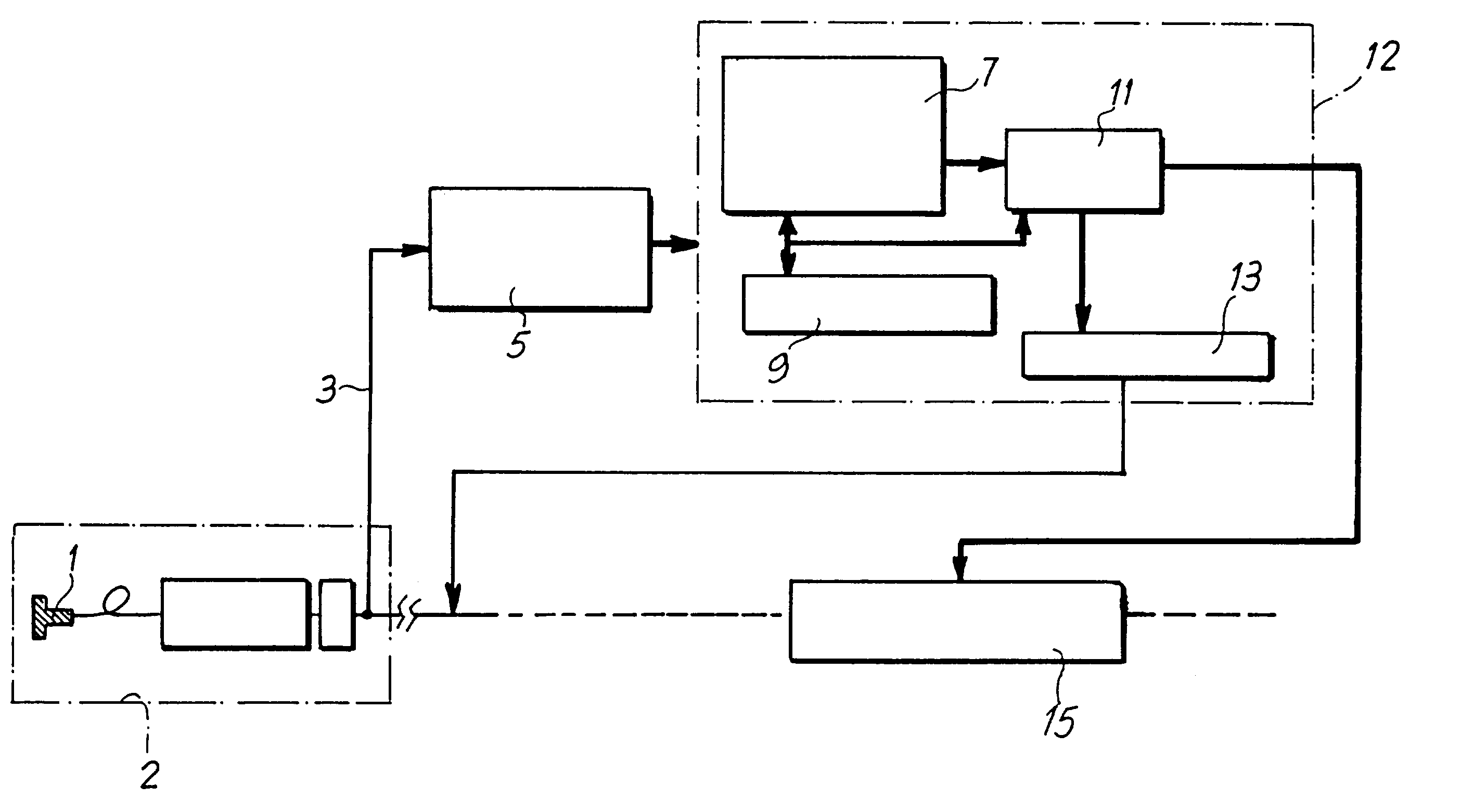
[0085]FIG. 5 shows a highly schematic block diagram of an echographic apparatus. The number 1 indicates a transducer of the scanning head, indicated in a general way by 2, which emits the echographic excitation signal and receives the echographic response signal. The analog output 3 of the scanning head is connected to an acquisition card 5. This generates a sampled and digitized radio frequency signal, which forms the input for a bank of integrated FIR filters, indicated in a general way by 7. The bank of filters 7 can consist of any commercially available integrated device, for example the 43168 circuit produced by Harris, the GF 191 circuit produced by Gennum, the GEC 16256 circuit produced by Plessey, or the GC2011 circuit produced by Graychip. The FIR filter 7 is associated with a digital signal processor (DSP) indicated by 9, which acts as a controller for the whole processing unit. The microcontroller 9 can be, for example, a TMS 3203...
PUM
 Abstract
Description
Claims
Application Information
 - R&D
- Intellectual Property
- Life Sciences
- Materials
- Tech Scout
- Unparalleled Data Quality
- Higher Quality Content
- 60% Fewer Hallucinations
Browse by: Latest US Patents, China's latest patents, Technical Efficacy Thesaurus, Application Domain, Technology Topic, Popular Technical Reports.
© 2025 PatSnap. All rights reserved.Legal|Privacy policy|Modern Slavery Act Transparency Statement|Sitemap|About US| Contact US: help@patsnap.com


