Layout structure of server chassis

Inactive Publication Date: 2011-04-28
INVENTEC CORP
View PDF8 Cites 4 Cited by
  • Summary
  • Abstract
  • Description
  • Claims
  • Application Information

AI Technical Summary

Benefits of technology

[0009]Accordingly, the present invention is directed to a new architecture layout structure for a server chassis that has improved commonality and reduced fabrication cost.
[0026]In view of the foregoing, in the server chassis layout structure of embodiments of the present invention, with the interengagement between the coupling portion of the partition plate and the coupling portions of the power backplane and the support member, the power supply module can be removably assembled to the partition plate of the chassis body. This enables the chassis body to share the electronic components that are used with chassis bodies of other specifications, thus improving the commonality as sell as reducing the fabrication cost of the chassis body of the server of the present invention.

Problems solved by technology

However, the chassis of the rackmount server has typically already been filled with electronic components and heat dissipating devices.
Therefore, this type of server is often limited by its expandability and heat dissipating problem.
Screen work must be done to screen out usable components and full expansion of the server generally cannot be achieved.
Therefore, one single server has only a limited performance and a limited application scope.
However, not all added expansion cards can receive power from the server.
A frequently encountered problem is that it is necessary to additionally provide a power supply for the expansion card.
As a result, under the condition that reconfiguration of the circuitry and components on the motherboard is impossible, users often have to give up the expansion card or otherwise arrange an independent power supply outside the server cabinet.
However, arranging an independent power supply outside the server cabinet would destroy the space-saving advantage of the rackmount server because the independent power supply needs additional space.

Method used


Image

  • Layout structure of server chassis
  • Layout structure of server chassis
  • Layout structure of server chassis

Examples


Embodiment Construction

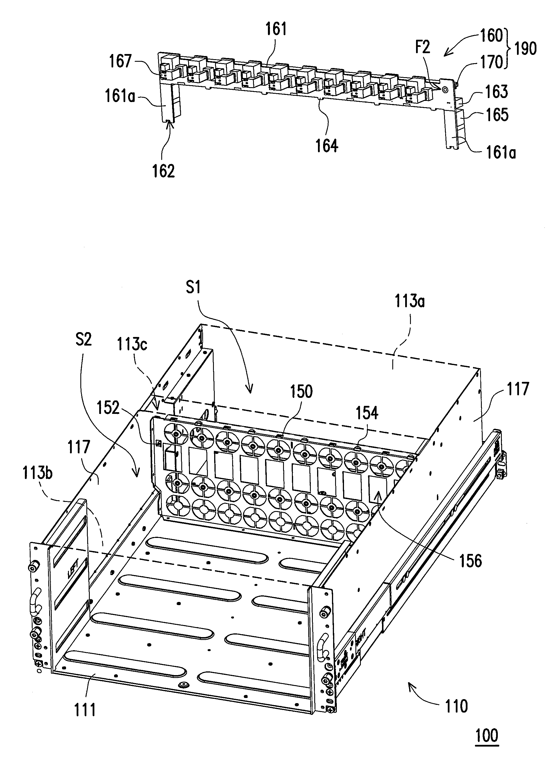
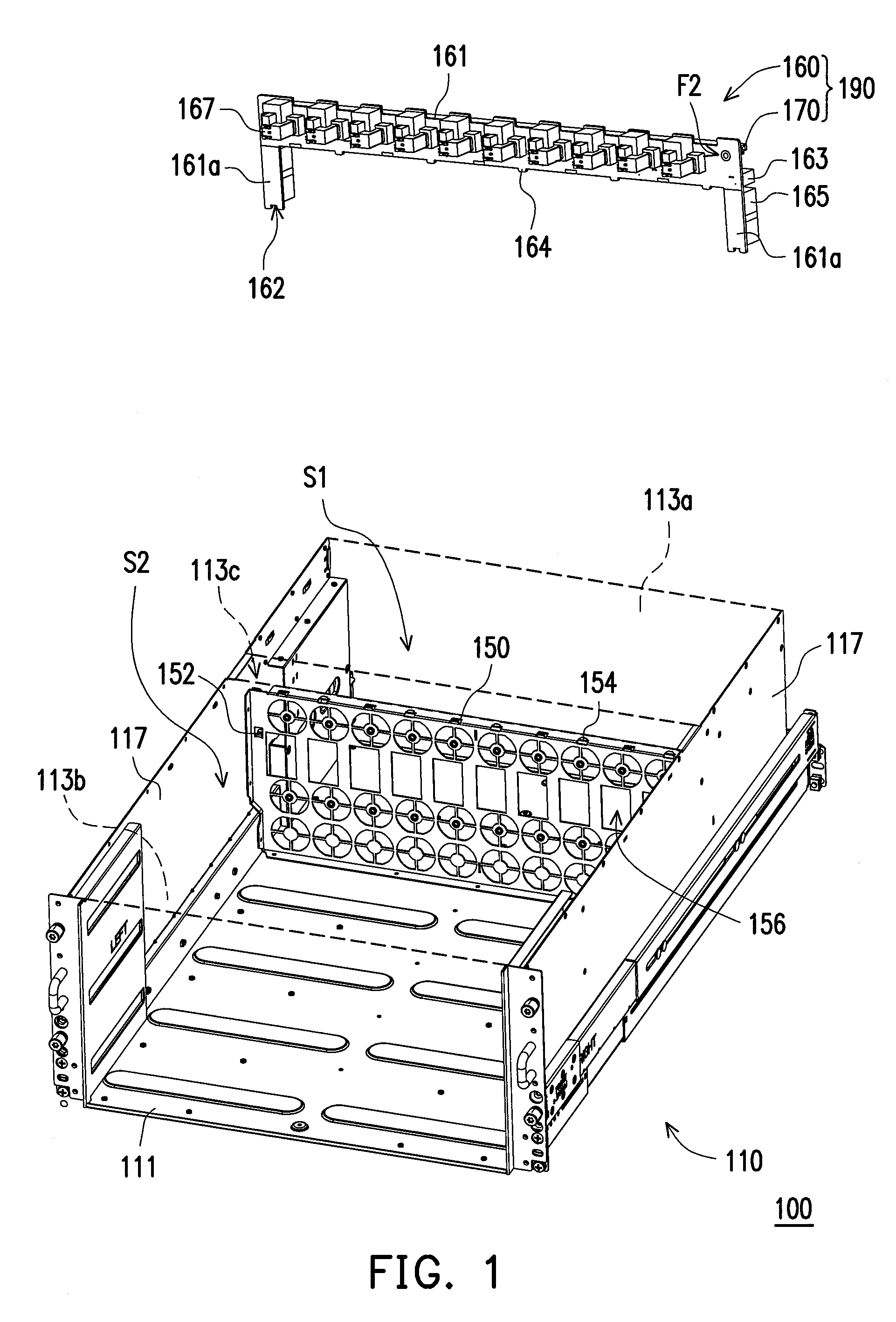
[0036]FIG. 1 illustrates a layout structure of a server chassis according to one embodiment of the present invention. Referring to FIG. 1, while a 5U server is taken as an example in the present embodiment, the principle of the present invention could be equally applied to a server of another specification. The server chassis layout structure 100 includes a chassis body 110, a partition plate 150, and a power backplane module 190. The chassis body 110 includes a bottom plate 111, a first top plate 113a, a second top plate 113b, and a pair of side plates 117. Both the first top plate 113a and the second top plate 113b are positioned opposite to the bottom plate 111, and a first opening 113c is formed between the first top plate 113a and the second top plate 113b. The side plates 117 are perpendicularly mounted between the bottom plate 111 and the top plates 113a, 113b. The side plates 117 are disposed at opposite sides of the first opening 113c. The partition plate 150 includes at le...


PUM


Abstract

A server chassis layout structure includes a chassis body, a partition plate, and a power backplane module. The chassis body includes a bottom plate, first and second top plates, and two side plates. The first and second top plates form a first opening therebetween. The side plates are mounted between the bottom and top plates. The partition plate includes at least one retaining portion and is perpendicularly fixed to the bottom plate below the first opening. The partition plate divides the chassis body into first and second sections. The power backplane module includes at least one lock portion and is vertically inserted into the chassis body via the first opening. The lock portion interferes with the retaining portion so as to assemble the power backplane module into the chassis body above the partition plate, and both the power backplane and the partition plate are exposed via the first opening.

Description

CROSS-REFERENCE TO RELATED APPLICATION[0001]This application claims the priority benefit of China application serial no. 200910209163.X, filed Oct. 28, 2009. The entirety of the above-mentioned patent application is hereby incorporated by reference herein and made a part of specification.BACKGROUND OF THE INVENTION[0002]1. Field of the Invention[0003]The present invention relates to a layout structure of a server chassis, and more particularly, to a new architecture of a layout structure of a server chassis.[0004]2. Description of Related Art[0005]As a core computer serving various computers within a network system, the server provides the storage and print function for network users as well as enables the network users to share various network resources. The basic architecture of the server is generally the same as a personal computer, which consists of a central processing unit (CPU), a memory, I / O devices, or the like. Buses are used to interconnect these internal components. A n...

Claims


Application Information

Patent Timeline
IPC IPC(8): H05K7/00
CPCH05K7/18G06F1/183
Inventor HU, YONG-LIANGZHANG, YANGXU, JI-PENGCHENG, TSAI-KUEI
Owner INVENTEC CORP
Why Eureka
Try Eureka