
Wrap-around shielded writer with highly homogeneous shield material

a shield layer and shield material technology, applied in the direction of instruments, thin material processing, data recording, etc., can solve the problems of significant mismatch between material composition and moments of these layers, pole tip recession/protrusion may be very different between, and the local protrusion of the shield layer is reduced.

Active Publication Date: 2011-04-28
HEADWAY TECH INC
View PDF44 Cites 28 Cited by
  • Summary
  • Abstract
  • Description
  • Claims
  • Application Information

AI Technical Summary

Benefits of technology

[0018]A second object of the present invention is to eliminate the formation of domain walls at the interfaces between the TS, SS and LS portions of a four sided magnetic shield due to mismatches in either the materials or their moments, thereby eliminating wide area track erasures (WATE) that are associated with such domain walls.
[0019]A third object of the present invention is to reduce the pole tip protrusion for a magnetic writer that uses a low Bs high thickness combination for certain shield layers, such as the LS and TS.
[0020]A fourth object of the present invention is to achieve the above stated objects without diminishing the on-track and off-track performance of the head.

Problems solved by technology

As a result, there will be a significant mismatch in material compositions and moments for these layers, all of which are exposed at the ABS (air bearing surface) of the write head.
Several issues may arise as a result of materials and moment mismatches.
First, the pole tip recession / protrusion may be very different between the layers, as a result of hardness differences between the materials and lapping rate variations during the slider lapping process that defines the final ABS.
This may affect the magnetic spacing between the write pole and media during write operation, thereby adversely affecting performance.
Another issue associated with the material / moment mismatches between different shield layers is the formation of domain walls at the layer interfaces that may cause wide area track erasures (WATE).
An additional disadvantage of using low Bs materials in the LS and pole yoke layers is that in order to conduct the same amount of magnetic flux as a material with twice the value of Bs, would require twice the thickness.

Method used


Image

  • Wrap-around shielded writer with highly homogeneous shield material
  • Wrap-around shielded writer with highly homogeneous shield material
  • Wrap-around shielded writer with highly homogeneous shield material

Examples


Embodiment Construction

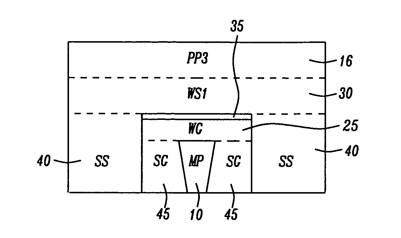
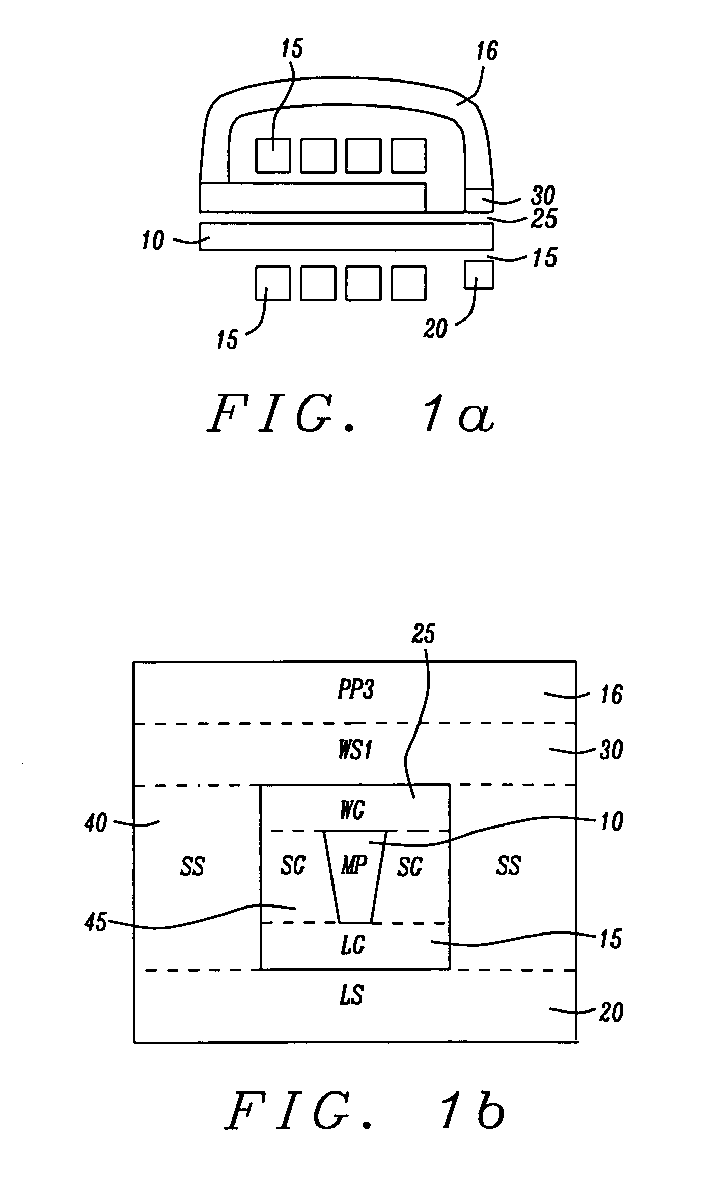
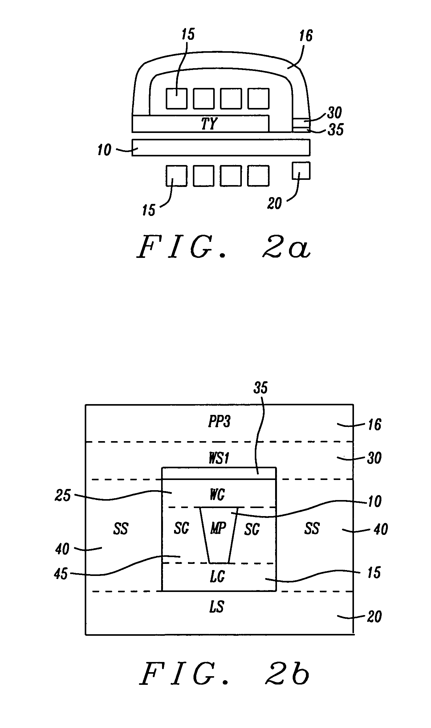
[0033]The preferred embodiment of the present invention is a shielded pole structure for use within a perpendicular magnetic recording (PMR) head, in which the shields are all formed of materials having substantially the same physical characteristics including the same material composition, the same hardness, the same response (eg. removal rate) to processes such as ion beam etching (IBE), chemical mechanical polishing (CMP), mechanical lapping, such as the slider ABS lapping, and the same coefficient of thermal expansion (CTE) as well as the same Bs. By “substantially the same,” is meant the fact that the physical characteristics (removal rate, CTE, BS) among the various layers and their seeds may have small variations on, the order of 10%, of their respective nominal values. For example, a nominal Bs of 2.0 T could have + / −0.1 T.

[0034]Referring first to FIG. 1a, there is shown a schematic side cross-sectional view of a typical inductive type PMR write head that is shielded in the ...


PUM

PropertyMeasurementUnit
widthaaaaaaaaaa
thicknessaaaaaaaaaa
thicknessaaaaaaaaaa

Abstract

A perpendicular magnetic recording (PMR) head is fabricated with a main pole shielded laterally by a pair of side shields, shielded above by a trailing shield and shielded optionally below by a leading shield. The shields and the seed layers on which they are formed are formed of materials having substantially the same physical characteristics including the same material composition, the same hardness, the same response to processes such as ion beam etching (IBE), chemical mechanical polishing (CMP), mechanical lapping, such as the slider ABS lapping, the same coefficient of thermal expansion (CTE) as well as the same Bs. Optionally, the trailing shield may be formed on a high Bs seed layer to provide the write head with improved down-track performance.

Description

BACKGROUND OF THE INVENTION[0001]1. Field of the Invention[0002]This invention relates to the fabrication of a perpendicular magnetic recording (PMR) write head whose main pole is surrounded on all sides by shields formed of magnetic material. In particular it relates to the formation of such shields using layers of the same magnetic material so that a consistent fabrication process can be employed and so that a corresponding consistent performance can be obtained.[0003]2. Description of the Related Art[0004]The increasing need for high recording area densities (up to 500 Gb / in2) is making the perpendicular magnetic recording head (PMR head) a replacement of choice for the longitudinal magnetic recording head (LMR head).[0005]By means of fringing magnetic fields that extend between two emerging pole pieces, longitudinal recording heads form small magnetic domains within the surface plane of the magnetic medium (hard disk). As recorded area densities increase, these domains must corr...

Claims


Application Information

Patent Timeline
Patent Type & Authority Applications(United States)
IPC IPC(8): G11B5/33
CPCG11B5/1278G11B5/315Y10T428/1171G11B5/112G11B5/6082G11B5/3163
Inventor BAI, ZHIGANGWU, YANDOVEK, MORISHAN, CHERNG CHYI
Owner HEADWAY TECH INC
Learn More