Multiple-sided cmp pad conditioning disk

a technology of conditioning disk and cmp pad, which is applied in the direction of grinding drive, grinding surface conditioning device, manufacturing tools, etc., can solve the problems of increased requirements for high-precision surface quality of wafers, unusability of wafers, and undesirable surface irregularities

Inactive Publication Date: 2011-04-28
ABRASIVE TECH
View PDF97 Cites 68 Cited by
  • Summary
  • Abstract
  • Description
  • Claims
  • Application Information

AI Technical Summary

Benefits of technology

[0020]The invention thus effectively provides two useful abrasive conditioning surfaces per disk

Problems solved by technology

As the size of the circuit components decreases and the complexity of the microstructures involved increases, the requirement for high precision surface qualities of the wafers increases.
Additionally, with continued use, the surface of the polishing pad normally experiences uneven wear which results in undesirable surface irregula

Method used


Image

  • Multiple-sided cmp pad conditioning disk
  • Multiple-sided cmp pad conditioning disk
  • Multiple-sided cmp pad conditioning disk

Examples


Embodiment Construction

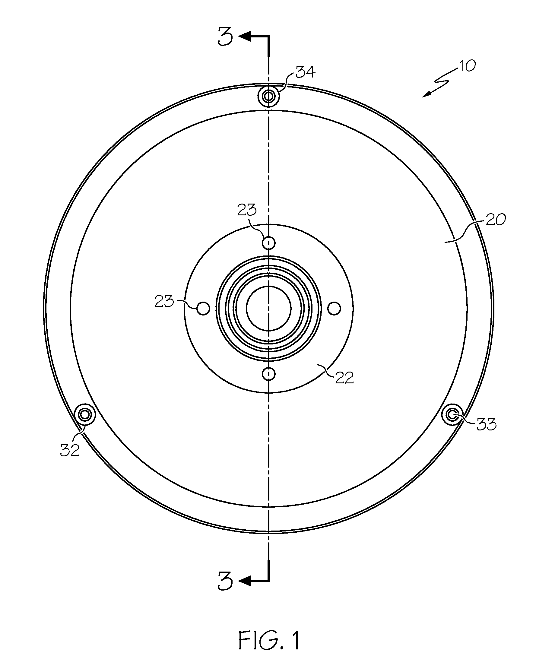
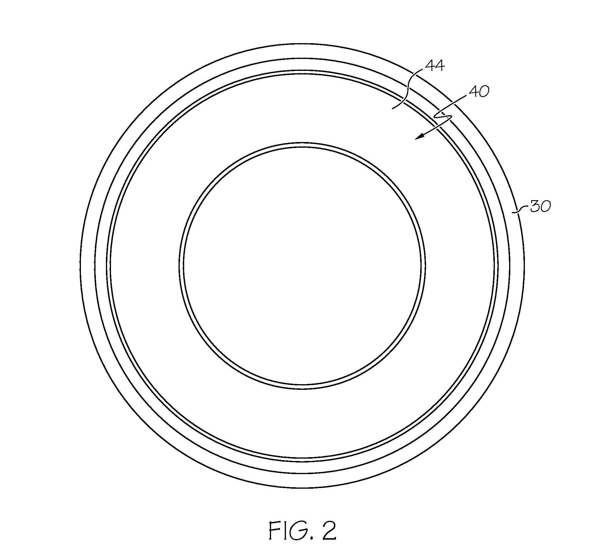
[0049]The preferred embodiment of the present invention includes the following major components that are illustrated in FIGS. 1-10. A holder 10 is made up of a base 20 and a ring 30 that attaches to the base 20. The base 20 is designed to be attached to a drive mechanism (not shown), such as a rotatable drive motor. The ring 30 rigidly and firmly attaches to the base 20 using fasteners, such as screws or magnets. A disk 40 is mounted between the ring 30 and the base 20, and is held in place in a tight, non-rotatable connection preferably by structures located at the peripheral edge of the disk 40 and the ring 30 or base 20 that interlock to prevent relative movement of the disk 40 and the holder 10. In this manner, the disk 40 is held firmly in place in the holder 10, and is driven rotatably thereby without substantial relative rotational movement between the disk 40 and the holder 10. This permits the disk surface to be placed in contact with a CMP polishing pad for conditioning th...


PUM

PropertyMeasurementUnit
Forceaaaaaaaaaa
Diameteraaaaaaaaaa
Abrasiveaaaaaaaaaa

Abstract

A conditioning tool for restoring a used CMP polishing pad to an operable condition. The tool includes a base that attaches to a driven machine and has a surface from which a shoulder protrudes that receives a peripheral edge of a disk. The disk has two opposing surfaces, each of which is substantially planar and has abrasive mounted thereon. The disk's peripheral edge is held in place between the base shoulder and a ring that has a shoulder that is complementary to the disk's peripheral edge. The ring is fastened to the base with the abrasive of the first disk surface protruding through an aperture in the ring, and the opposing disk surface spaced from the base's surface. After the disk's first surface is worn, the disk can be turned around to expose the opposite surface's abrasive to a CMP pad.

Description

BACKGROUND OF THE INVENTION[0001]1. Field Of The Invention[0002]This invention relates generally to methods and apparatuses related to the polishing of workpieces, such as semiconductor wafers, and particularly to an improved disk or other shape substrate for conditioning and restoring polishing pads used in such methods.[0003]2. Description Of The Related Art[0004]The production of integrated circuits involves the manufacture of high quality semiconductor wafers. As well known in this industry, a surface that is flat (planar) to a high degree of precision is required on at least one side of the wafer to ensure that appropriate performance objectives are achieved. As the size of the circuit components decreases and the complexity of the microstructures involved increases, the requirement for high precision surface qualities of the wafers increases.[0005]This high precision surface is formed on semiconductor wafers by the polishing or planarization of semiconductor wafers. During thi...

Claims


Application Information

Patent Timeline
IPC IPC(8): B24B53/02B24B53/12
CPCB24B53/12B24B53/017
Inventor BUBNICK, MARK L.NAMOLA, JR., THOMAS S.
Owner ABRASIVE TECH
Why Eureka
Try Eureka