
Function decomposition and control architecture for complex vehicle control system

a control system and complex technology, applied in anti-collision systems, non-deflectable wheel steering, underwater vessels, etc., can solve the problems of resource and objective conflict, complex process of design and integration of these various devices and sub-systems, and overlap in functional functions

Inactive Publication Date: 2011-04-28
GM GLOBAL TECH OPERATIONS LLC
View PDF10 Cites 55 Cited by
  • Summary
  • Abstract
  • Description
  • Claims
  • Application Information

AI Technical Summary

Benefits of technology

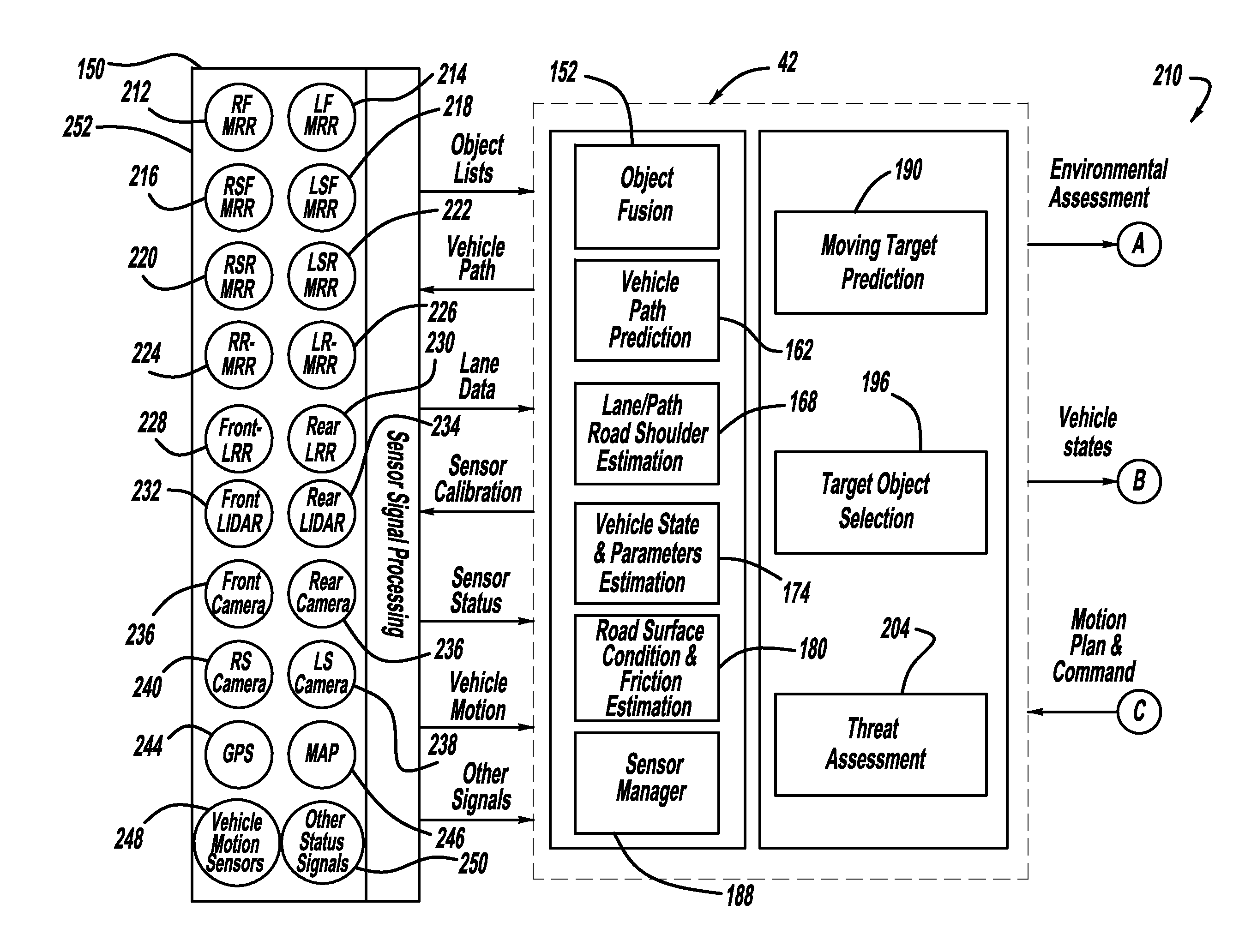
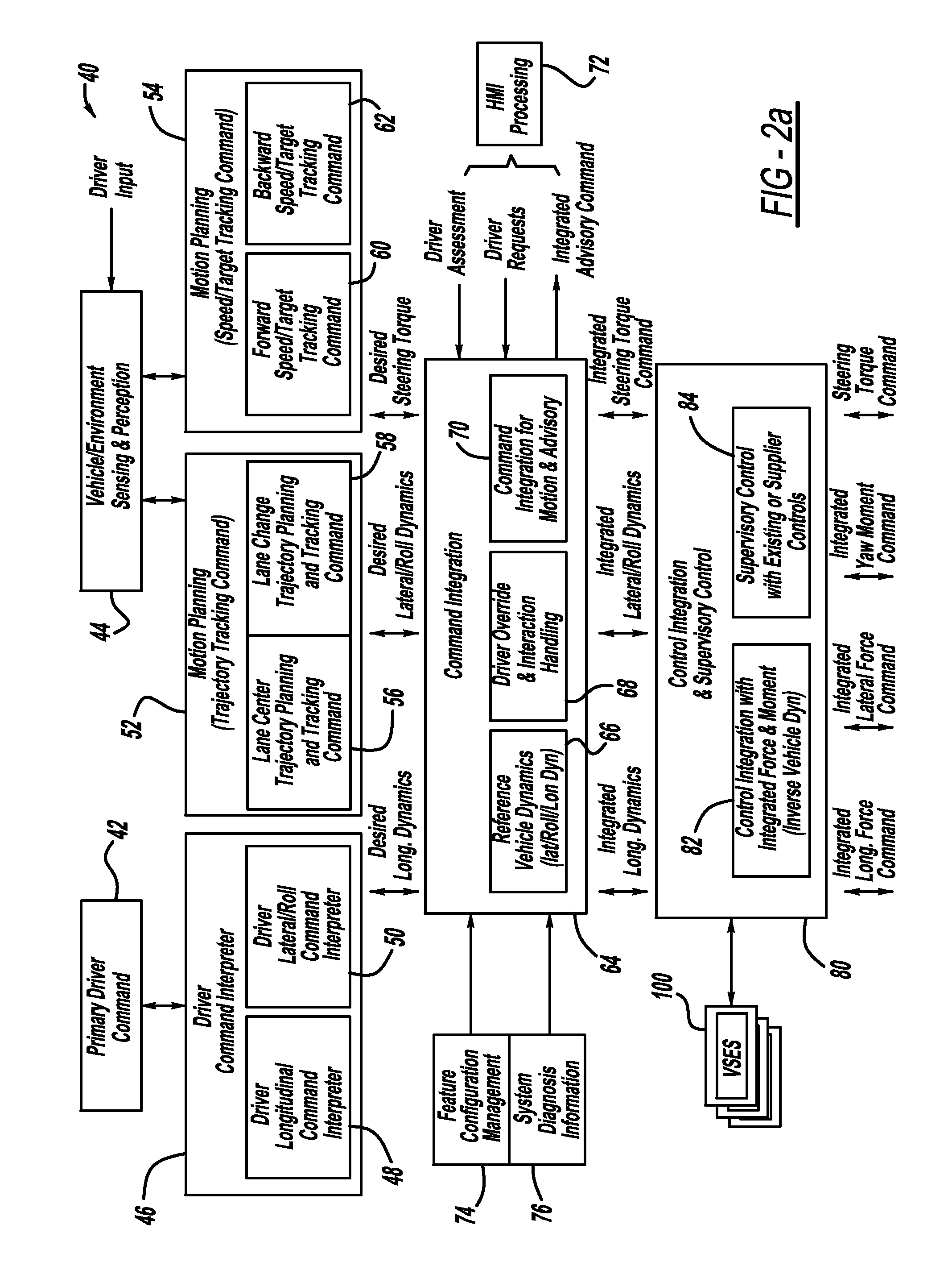
The present invention is a vehicle control architecture that uses a top-down approach to process sensor signals from various devices, such as cameras, radar, and inertia measurement units, to plan and track the vehicle's trajectory. The architecture includes a driver command interpreter to interpret the driver's steering, braking, or throttle command and output desired vehicle dynamics signals. A command integration processor receives the desired vehicle dynamics signals and outputs integrated commands with vehicle forces and yaw moment. A supervisory controller handles existing or supplier-provided modules, such as ABS, TCS, and ESC. The architecture also includes a vehicle longitudinal controller and a vehicle lateral controller to output the necessary signals to control the vehicle's longitudinal and lateral movement. The technical effect of this invention is to provide a more efficient and effective vehicle control system that improves safety and driver experience.

Problems solved by technology

The design and integration of these various devices and sub-systems is a complex process that requires many different components and modules to interact with each other in an efficient and reliable manner.
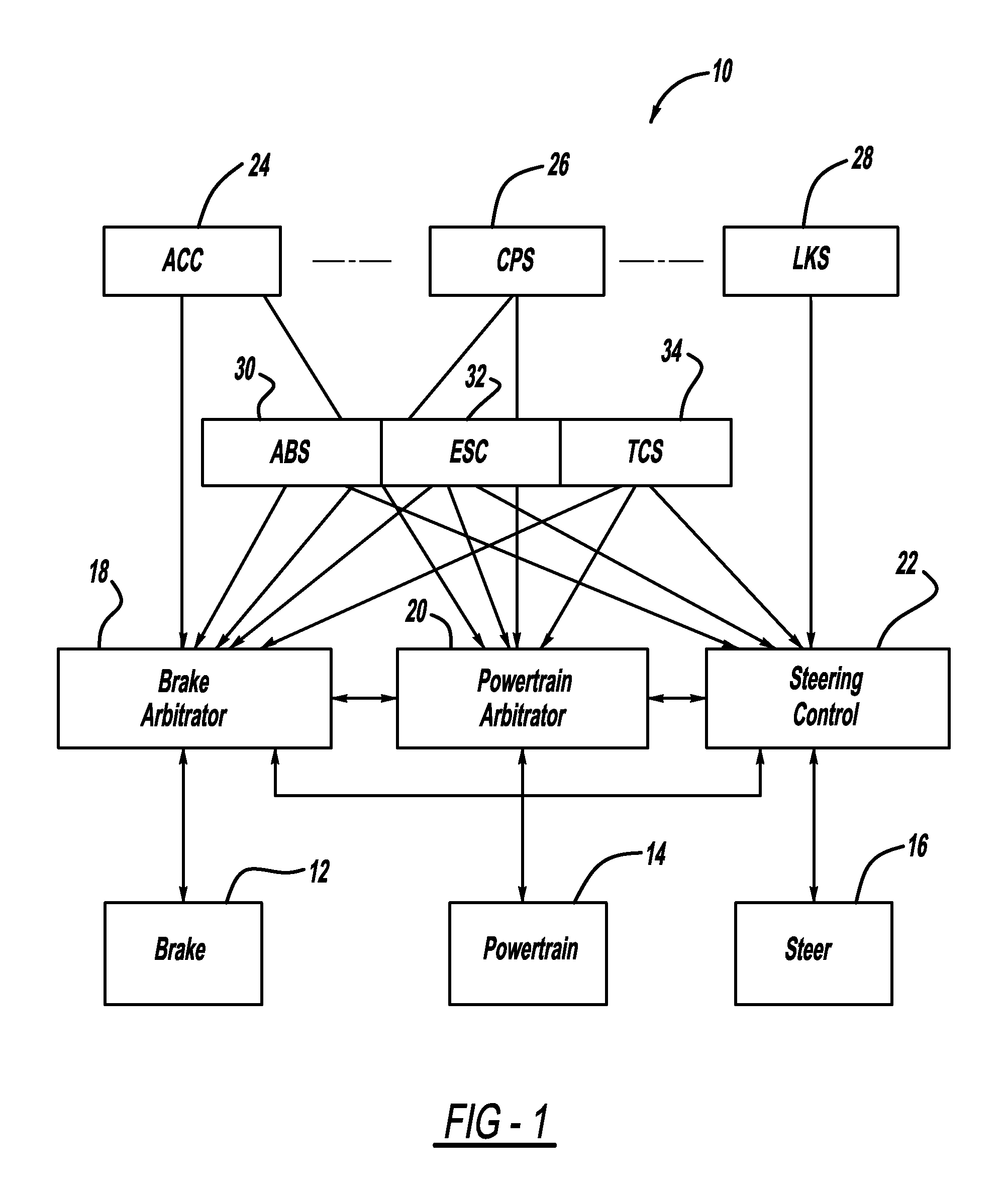
Such a design process often results in resource and objective conflicts and a functional overlap between different component features and sub-systems that requires arbitrated control.
Further, arbitrated control often leads to performance trade-offs or even conflict.
Also, such a design technique tends to be more hardware dependent and has a lack of coordination and sharing of resources.
Further, conventional vehicle control systems are mainly for driver-commanded vehicle dynamics, including ride, handling and stability, and lack of the ability to handle driver assist and active safety features, and sensor-guided autonomous or semi-autonomous driving with environmental sensors.
The above-described conventional vehicle control systems are designed in a bottom-up based design approach in which features are developed one at a time, and added to the over-all system one-by-one, which often leads to system complication, unmanageability and lack of optimization.
These systems are mainly feedback based with trial and error approaches, and often limit their applications to near-limit or non-linear operating regions.
Typically, they are hardware dependent, with feature-based design from end-to-end that often limits reusability among common functionalities, and flexibility for fault tolerance, electrical architecture and supplier sourcing.
Arbitrated controls are typically applied among the features that often lead to potential conflict and performance trade off.
Thus, as more elements are added to the control system, the ability to provide such validation becomes more complex and costly.
Therefore, because each supplier develops their components independent of each other, the complexity of integrating the components becomes much more complex, and the ability to interchange one supplier's component with another becomes problematic.
Further, such a design strategy causes a number of duplications.

Method used


Image

  • Function decomposition and control architecture for complex vehicle control system
  • Function decomposition and control architecture for complex vehicle control system
  • Function decomposition and control architecture for complex vehicle control system

Examples


Embodiment Construction

[0015]The following discussion of the embodiments of the invention directed to a vehicle control architecture that is designed in a top-to bottom manner is merely exemplary in nature, and is in no way intended to limit the invention or its applications or uses.

[0016]As will be discussed in detail below, the present invention proposes a functional decomposition and control architecture for a vehicle that is commanded by integrated driver commands coordinated with sensor-guided assist controls to provide smoother activation and transition with less intrusion to the driver and fully integrated driver-vehicle-environment control. The proposed control architecture provides a top-down and synthesis-based design approach with system integration to provide a feed-forward dominate control that minimizes trial and error with faster control response and full operation regions for stability, comfort and performance. The control architecture reduces or eliminates confusion, uncertainty or indete...


PUM


Abstract

A vehicle control architecture designed based on a top-down approach with abstraction and modularity. The control architecture includes a vehicle / environment sensing and perception processor that processes sensor signals, and motion planning processors that provide lane center trajectory planning and tracking command, lane change trajectory planning and tracking command, and forward and backward speed and target tracking command. The architecture also includes a driver command interpreter that interprets driver commands and a command integration processor that provides reference dynamics for vehicle lateral, roll and longitudinal dynamics. The architecture also includes a control integration and supervisory controller that provides control integration and outputs integrated longitudinal force command signals, integrated lateral force command signals, integrated yaw moment command signals and steering torque command signals that are used by a vehicle longitudinal controller and a vehicle lateral controller.

Description

BACKGROUND OF THE INVENTION[0001]1. Field of the Invention[0002]This invention relates generally to a control architecture for a vehicle system and, more particularly, to a control architecture for a complex vehicle control system that is designed in a hierarchical manner from top to bottom.[0003]2. Discussion of the Related Art[0004]Modern vehicles are complex electrical and mechanical systems that include many different parts and sub-systems, such as actuators, sensors, controllers, communication buses, etc., that are integrated in a hierarchical configuration. The design and integration of these various devices and sub-systems is a complex process that requires many different components and modules to interact with each other in an efficient and reliable manner.[0005]Conventional vehicle control systems, such as anti-lock brake system (ABS), traction control system (TCS), electronic stability control system (ESC), etc., are typically developed independently of each other and are ...

Claims


Application Information

Patent Timeline
Patent Type & Authority Applications(United States)
IPC IPC(8): B60W10/00B60W10/18B60W10/20B60W10/06B60W10/10G05D1/00G08G1/16
CPCB60W10/04B60W10/18B60W10/20Y10T477/6394B60W2050/0006G08G1/16B60W50/0098G08G1/165G08G1/166G08G1/167
Inventor DENG, WEIWEN
Owner GM GLOBAL TECH OPERATIONS LLC
Learn More