Wall-mounted attaching apparatus

a wall-mounted and attaching technology, which is applied in the direction of washstands, scaffold accessories, lighting supports devices, etc., can solve the problems of difficult to fix the wall-mounted attaching apparatus itself on the wall surface correctly, and the work of fixing the wall-mounted attaching apparatus itself on the wall surface is relatively long and effort, so as to facilitate the work of fixing

Inactive Publication Date: 2011-05-05
MITSUBISHI ELECTRIC CORP
View PDF12 Cites 17 Cited by
  • Summary
  • Abstract
  • Description
  • Claims
  • Application Information

AI Technical Summary

Benefits of technology

[0008]An object is to obtain a wall-mounted attaching apparatus that facilitates the work of fixing the wall-mounted attaching apparatus itself on a wall surface and that enables the wall-mounted attaching apparatus itself to be fixed on the wall surface correctly according to the original design.
[0011]The hung opening can be hung with a given mounting hardware provided on the wall surface. The plurality of fixing screw holes are provided to fix the frame body by screwing on the wall surface, and the plurality of fixing screw holes have given screwing position freedom.
[0012]According to the wall-mounted attaching apparatus of the present invention, a plurality of wall-mounted attaching apparatuses for installing given display apparatuses in a multiple arrangement manner can be easily and correctly attached.

Problems solved by technology

Conventional wall-mounted attaching apparatuses are structured as above, and the work of fixing the wall-mounted attaching apparatus itself on the wall surface relatively take time and effort, and it is difficult to fix the wall-mounted attaching apparatus itself on the wall surface correctly according to the original design.

Method used


Image

  • Wall-mounted attaching apparatus
  • Wall-mounted attaching apparatus
  • Wall-mounted attaching apparatus

Examples


Embodiment Construction

[0040]

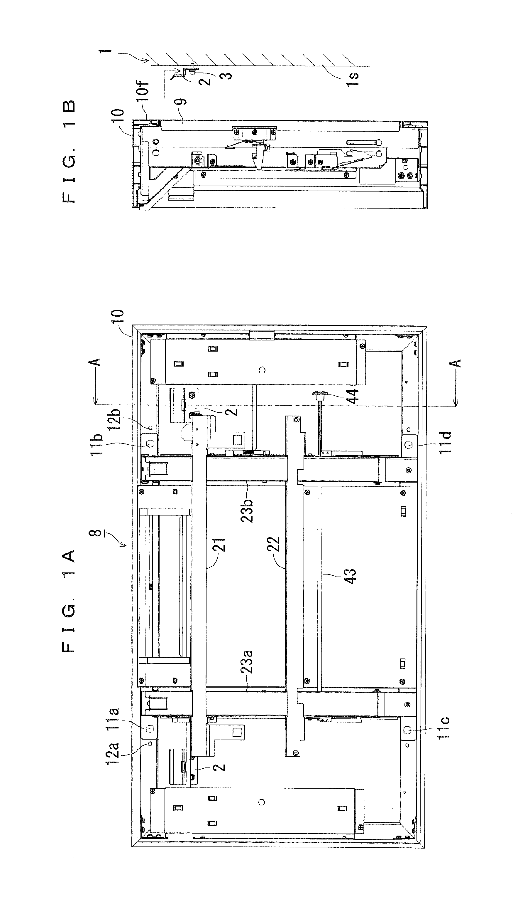
[0041]FIGS. 1A and 1B are illustrative diagrams showing the structure of a wall-mounted attaching apparatus according to a preferred embodiment of the present invention. FIG. 1A shows the top view (the structure seen from the side where a thin display is installed), and FIG. 1B shows the A-A section of FIG. 1A.

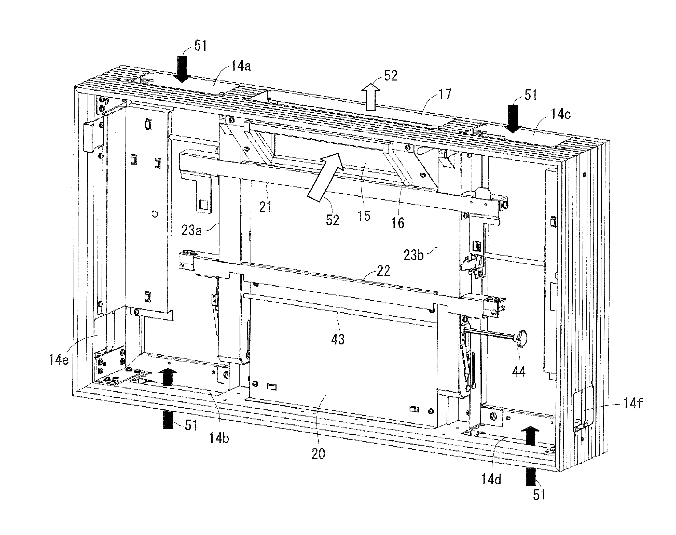
[0042]As shown in FIG. 1A, the wall-mounted attaching apparatus 8 includes a display apparatus attaching portion including horizontal front bars 21 and 22, vertical front bars 23a and 23b, a shaft 43, a knob 44, etc. provided in a mount portion 10 as a frame body, and an exhaust portion (not shown in FIGS. 1A and 1B). Illustrative diagrams of the display apparatus attaching portion and the exhaust portion will be described later in detail.

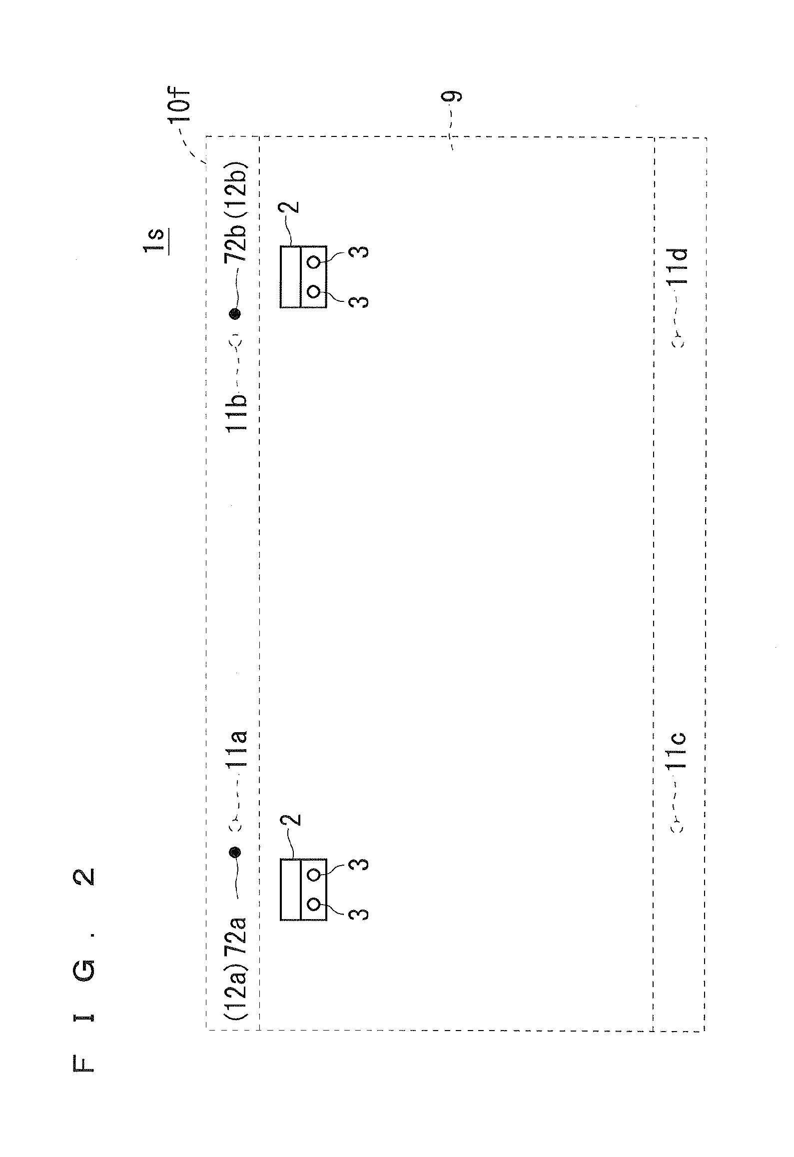
[0043]The outside shape of the mount portion 10 is rectangular, and its installation surface has mount fixing holes 11a and 11b in an upper part, and mount fixing holes 11c and 11d in a lower part. Also, default positioning holes 12a an...


PUM


Abstract

A mount portion has a rectangular outside shape, and has an opening in its center part that can be fitted by hanging on mounting brackets fixed on a wall surface. An installation surface has mount fixing holes in its upper part and mount fixing holes in its lower part. Default positioning holes are provided adjacent to the mount fixing holes. In screwing, the mount fixing holes have given screwing position freedom. The regions of the default positioning holes have smaller opening areas than the regions of the mount fixing holes.

Description

BACKGROUND OF THE INVENTION[0001]1. Field of the Invention[0002]The present invention relates to a wall-mounted attaching apparatus for use with a display apparatus such as a thin display.[0003]2. Description of the Background Art[0004]Usually, when installing a display apparatus, such as a thin display, on a wall surface, a wall-mounted attaching apparatus for attaching the display apparatus is previously fixed on the wall surface, and then the display apparatus is attached to the wall-mounted attaching apparatus.[0005]Such wall-mounted attaching apparatuses include the thin display wall mounting apparatus disclosed in Japanese Patent Application Laid-Open No. 2006-53212 (FIG. 6), for example.[0006]This wall-mounting apparatus has a base plate fixed on a wall surface and an attaching frame previously attached to the back of a thin display. Engaging pins provided in upper and lower portions of the back of the attaching frame are detachably joined to supporting beams provided on the ...

Claims


Application Information

Patent Timeline
Patent Type & Authority Applications(United States)
IPC IPC(8): F16M13/02
CPCF16M11/048F16M13/02F16M2200/066F16M2200/061F16M2200/02
Inventor KITAGUCHI, AKIHIRO
Owner MITSUBISHI ELECTRIC CORP
Why Eureka
Try Eureka