Resonant transformer

a transformer and resonance technology, applied in the direction of transformer/inductance coil/winding/connection, transformer/inductance details, electrical equipment, etc., can solve the problems of inability to stably control the leakage inductance of the transformer b>1/b>, and the difficulty of minimizing the conventional transformer b>1/b>, so as to increase the winding space, enhance the effect of electric conversion efficiency and control the leakage inductan

Inactive Publication Date: 2011-05-05
DELTA ELECTRONICS INC
View PDF4 Cites 3 Cited by
  • Summary
  • Abstract
  • Description
  • Claims
  • Application Information

AI Technical Summary

Benefits of technology

[0008]Another object of the present invention provides a resonant transformer having an air gap disposed over the primary winding coil, thereby stably controlling the leakage inductance.
[0009]A further object of the present invention provides a resonant transformer having increased winding space, enhanced electric conversion efficiency, and reduced heat generation.
[0010]A still object of the present invention provides a resonant transformer having plural modular bobbins connected with each other in parallel, so that the output voltage of the resonant transformer is increased.

Problems solved by technology

That is, it is difficult to minimize the conventional transformer 1.
Under this circumstance, the leakage inductance of the transformer 1 fails to be stably controlled.

Method used


Image

  • Resonant transformer
  • Resonant transformer
  • Resonant transformer

Examples


first embodiment

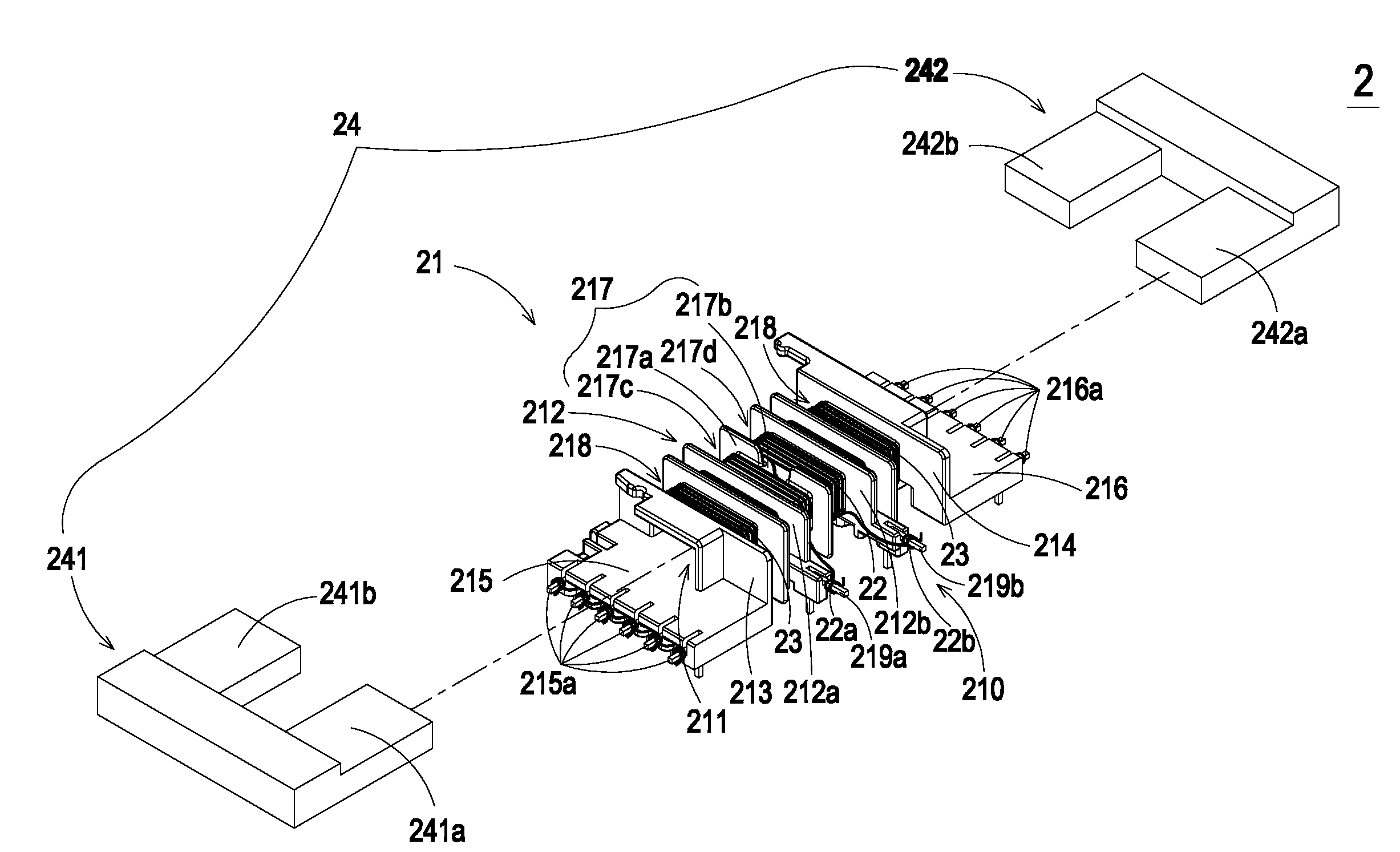
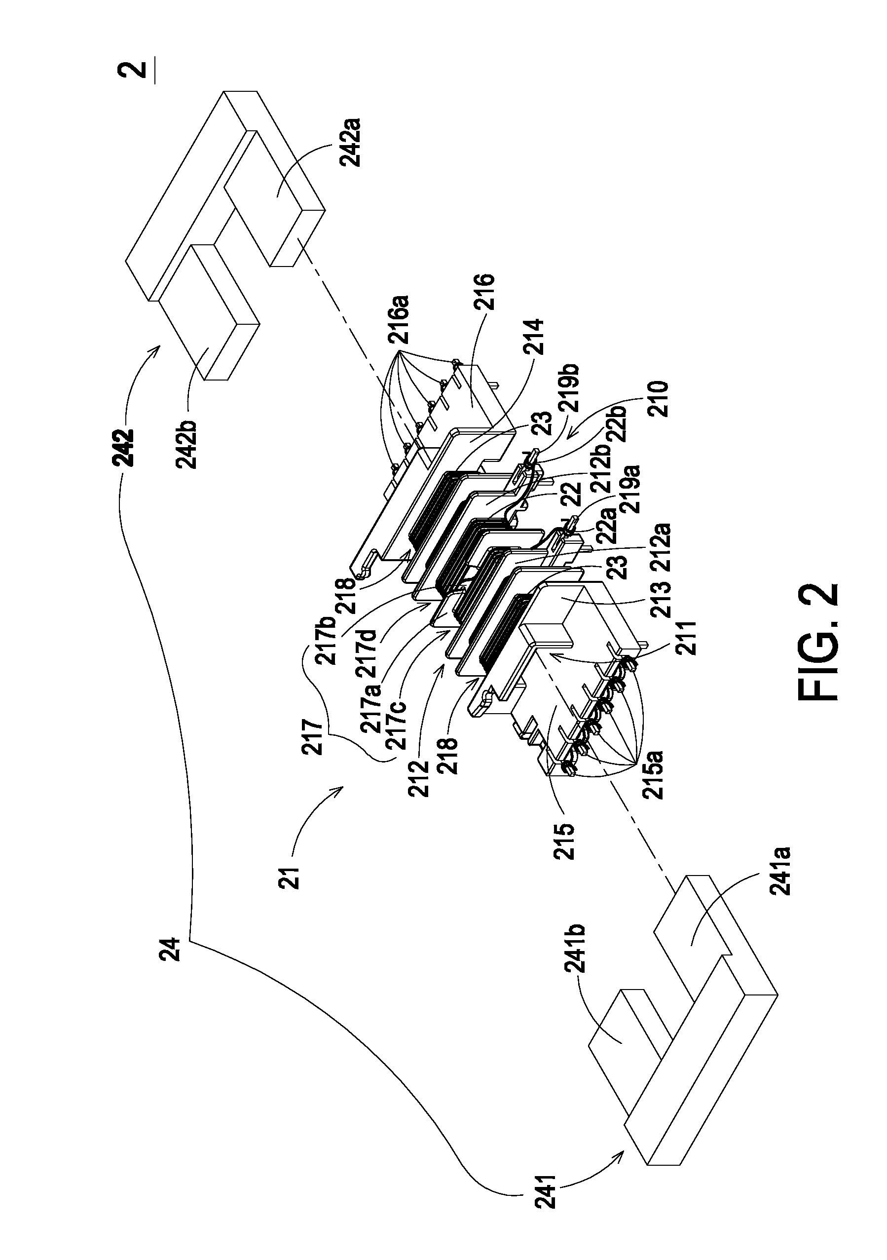
[0022]FIG. 2 is a schematic exploded view illustrating a resonant transformer according to the present invention. As shown in FIG. 2, the resonant transformer 2 comprises a bobbin 21, a primary winding coil 22, plural secondary winding coils 23, and a magnetic core assembly 24.

[0023]The bobbin 21 comprises a main body 210, a channel 211, plural partition plates 212, a first side plate 213, a second side plate 214, a first connecting base 215 and a second connecting base 216. The channel 211 runs through the main body 210. The main body 210 is substantially cylinder tube with a rectangular cross-section. The first side plate 213 and the second side plate 214 are respectively arranged at two opposite sides of the main body 210. The partition plates 212 are disposed on the main body 210, and arranged between the first side plate 213 and the second side plate 214. In addition, the partition plates 212 are substantially parallel to the first side plate 213 and the second side plate 214. ...

second embodiment

[0029]FIG. 3A is a schematic exploded view illustrating a resonant transformer according to the present invention. As shown in FIG. 3A, the resonant transformer 3 comprises a bobbin 31, a primary winding coil 32, plural secondary winding coils 33, and a magnetic core assembly 34.

[0030]The bobbin 31 comprises a main body 310, a first channel 311, plural partition plates 312, a first side plate 313, a second side plate 314, a first connecting base 315 and a second connecting base 316. By the first side plate 313, the second side plate 314 and the partition plates 312, a first winding section 317 and plural single-trough second winding sections 318 are collectively defined on the main body 310. The magnetic core assembly 34 comprises a first magnetic part 341 and a second magnetic part 342. The first magnetic part 341 of the magnetic core assembly 34 comprises a first leg portion 341a and a second leg portion 341b. The second magnetic part 342 of the magnetic core assembly 34 also comp...

third embodiment

[0033]FIG. 4A is a schematic exploded view illustrating a resonant transformer according to the present invention. As shown in FIG. 4A, the resonant transformer 4 comprises a first bobbin 41, a first primary winding coil 42, plural first secondary winding coils 43, a second bobbin 44, a second primary winding coil 45, plural second secondary winding coils 46, and a magnetic core assembly 47.

[0034]The first bobbin 41 comprises a first main body 410, a first channel 411, plural partition plates 412, a first side plate 413, a second side plate 414, a first connecting base 415 and a second connecting base 416. By the first side plate 413, the second side plate 414 and the partition plates 412, a first winding section 417 and plural single-trough second winding sections 418 are collectively defined on the first main body 410. The second bobbin 44 comprises a second main body 440, a second channel 441, plural partition plates 442, a third side plate 443, a fourth side plate 444, a third c...


PUM

PropertyMeasurementUnit
voltagesaaaaaaaaaa
distancesaaaaaaaaaa
creepage distancesaaaaaaaaaa

Abstract

A resonant transformer includes a bobbin, a primary winding coil, plural secondary winding coils, and a magnetic core assembly. The bobbin includes a main body and a channel running through the main body. The main body includes a first winding section and plural single-trough second winding sections. Plural pins are arranged at the first winding section. The single-trough second winding sections are arranged at bilateral sides of the first winding section. The primary winding coil is wound around the first winding section of the bobbin and connected with the pins. The secondary winding coils are wound around respective single-trough second winding sections of the bobbin. The magnetic core assembly is partially embedded into the channel of the bobbin.

Description

FIELD OF THE INVENTION[0001]The present invention relates to a resonant transformer, and more particularly to a slim resonant transformer.BACKGROUND OF THE INVENTION[0002]A transformer has become an essential electronic component for voltage regulation into required voltages for various kinds of electric appliances.[0003]In the power supply system of the new-generation electric products such as LCD televisions, leakage inductance transformers (e.g. LLC transformers) become more and more prevailing. The use of the leakage inductance transformer may reduce damage possibility of the switch, minimize noise and enhance performance.[0004]FIG. 1 is a schematic exploded view of a conventional leakage inductance transformer. As shown in FIG. 1, the transformer 1 comprises a bobbin 11, a covering member 12, and a magnetic core assembly 13. A primary winding coil 111 and a secondary winding coil 112 are wound around the bobbin 11. The output terminals 113, 114 of the primary and the secondary ...

Claims


Application Information

Patent Timeline
Patent Type & Authority Applications(United States)
IPC IPC(8): H01F27/29
CPCH01F27/324
Inventor TSAI, HSIN-WEICHANG, SHIH-HSIENTIEN, CHING-HSIANG
Owner DELTA ELECTRONICS INC
Why Eureka
Try Eureka