High-frequency module and wireless device

Inactive Publication Date: 2011-05-05
NEC CORP
View PDF6 Cites 8 Cited by
  • Summary
  • Abstract
  • Description
  • Claims
  • Application Information

AI Technical Summary

Benefits of technology

[0019]In the high-frequency module and the wireless device according to the invention, it is possible to improve the electric characteristics and to easily perform the assembling operation and the inspection operation without performing the soldering operation in the input-output connection of the high-frequency signal.

Problems solved by technology

However, in the input-output portion of the shielded high-frequency module, the following problem arises in the technology of soldering a coaxial cable such as a solid jacket cable including a coaxial connector to a substrate wiring.
That is, transmission loss increases with cable length, and hence the efficiency decreases.
Since a shield cover is required for the high-frequency signal and a soldering operation of the center conductor of the coaxial cable of the input-output portion is performed manually, the efficiency of the soldering operation is bad, and it is difficult to perform the assembling operation and the inspection operation are difficult to be performed.
In addition; since the coaxial cable exists between the modules, a problem arises in that a space used for wiring the cable is required and the device cannot be decreased in size.
Further, in the electronic-device-box coaxial connection assembly disclosed in Patent Document 5, a problem arises in that heat radiated by a highly heated component of the high-frequency module represented as a high-output amplifier or the like cannot be handled.
Furthermore, since the contact arm is limited to having the fork shape, a problem arises in that the contact arm cannot be used for various purposes.Patent Document 1: Japanese Utility Model Bulletin No.

Method used


Image

  • High-frequency module and wireless device
  • High-frequency module and wireless device
  • High-frequency module and wireless device

Examples


first embodiment

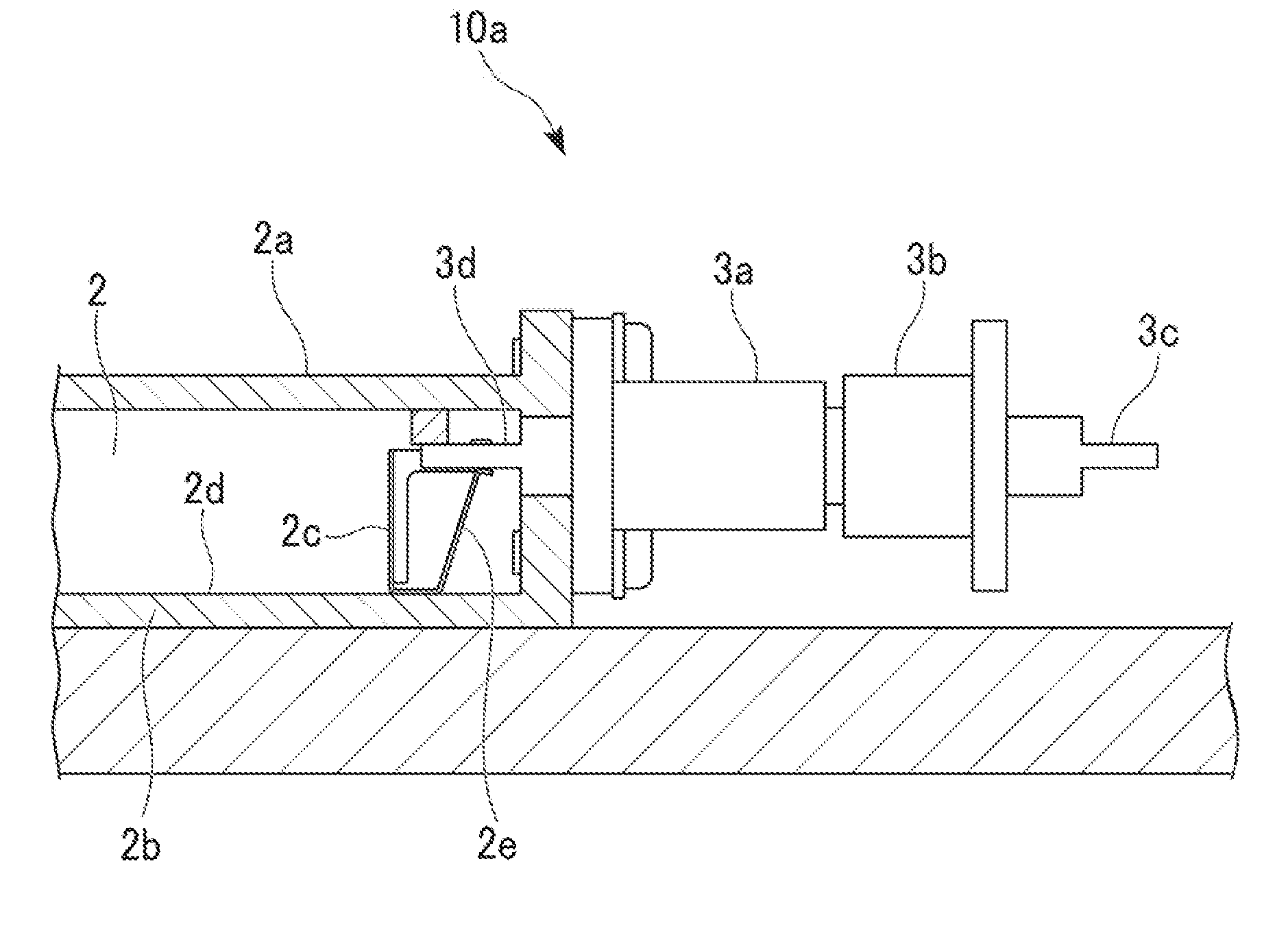
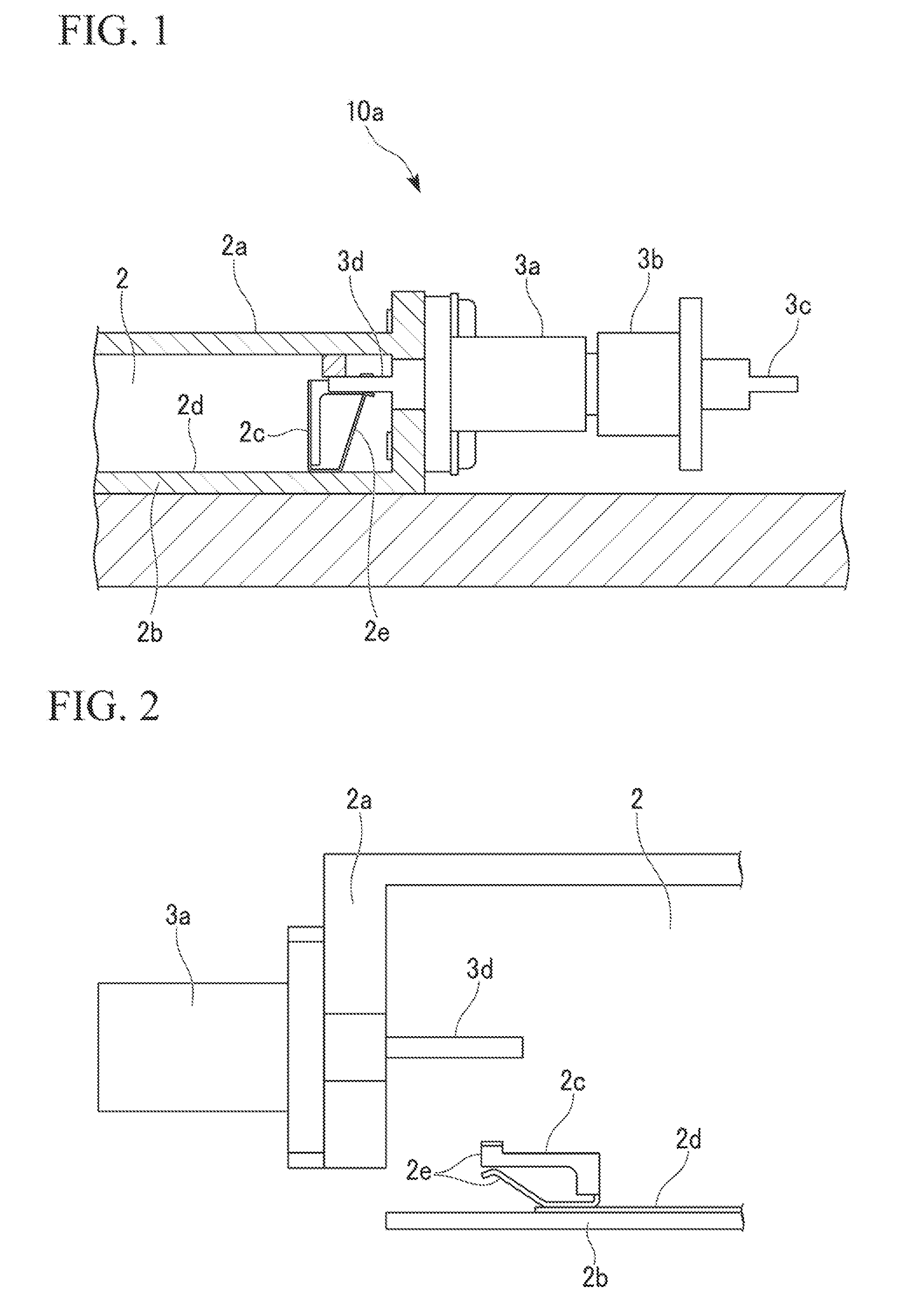
[0064]FIG. 2 is a side sectional view showing the structure of the high-frequency module 2 according to the invention. FIG. 2 shows the state before the center conductor 3d is connected to the metal plate terminal 2c. In FIG. 2, the coaxial connector 3a is fixed to the side surface of the shield cover 2a of the high-frequency module 2. The center conductor 3d of the coaxial connector 3a protrudes to the inside of the high-frequency module 2. The metal plate terminal 2c is mounted on the print wiring 2d formed on the substrate 2b by means of the SMD automatic mounting operation. As shown in FIG. 2, the shield cover 2a is fixed to the substrate 2b so as to cover the upper portion of the substrate. Accordingly, the center conductor 3d of the coaxial connector 3a is fitted between the arms 2e of the metal plate terminal 2c. That is, it is possible to simultaneously perform an attaching operation of the shield cover 2a and an input-output connection operation of the high-frequency signal...

second embodiment

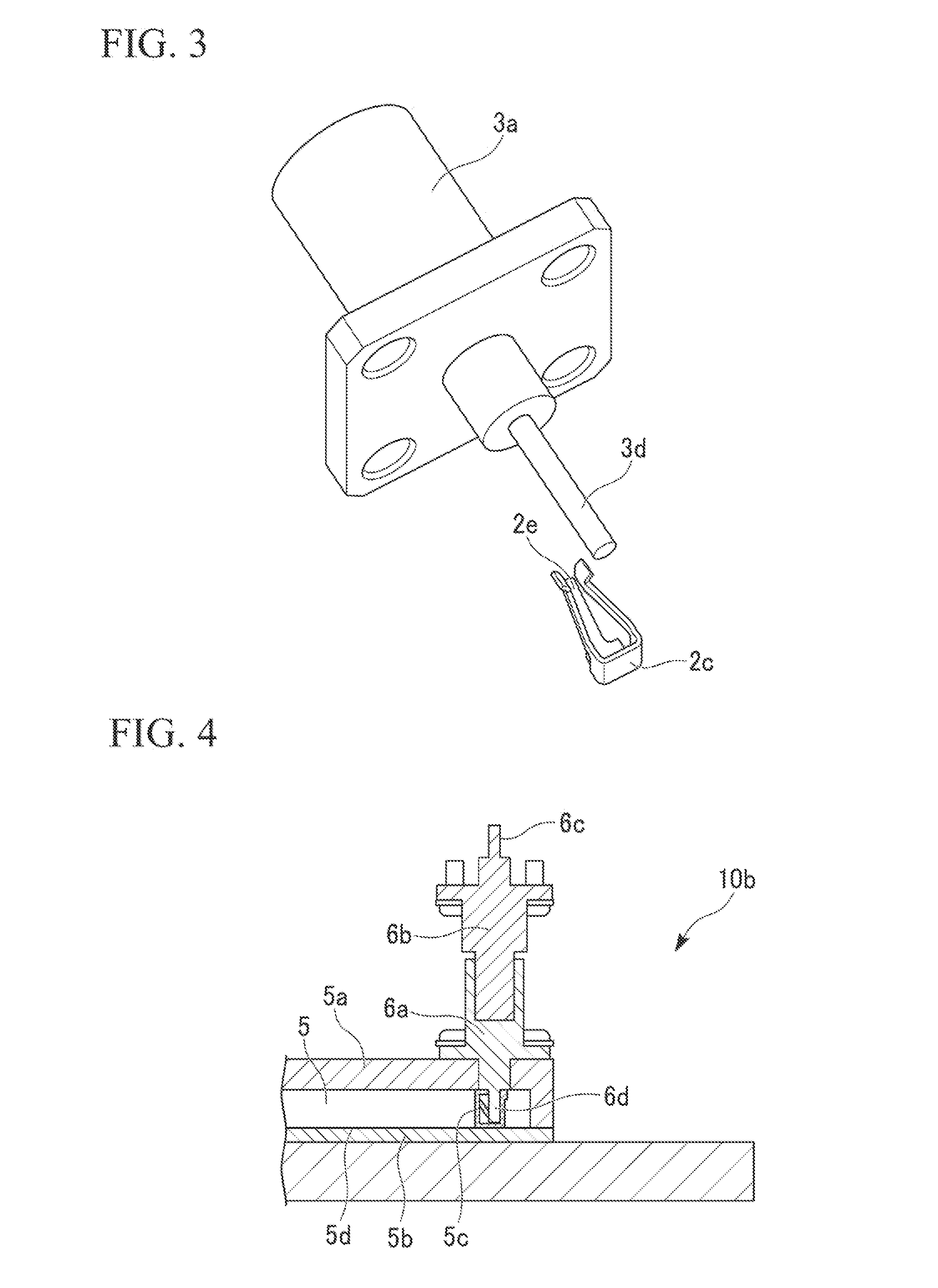
[0071]The high-frequency module 5 according to the invention is formed to have a vertical-type structure. That is, an axial direction of the center conductor 6d is parallel to the direction vertical to a surface of the substrate 5b. In the vertical-type structure, the fitting operation is performed in the axial direction of the center conductor 6d, and the stress acting on the center conductor 6d and the metal plate terminal 5c is reduced, thereby further improving long-time reliability.

[0072]In addition, in the second embodiment of the invention, the two-contact-point connection may be simplified in order to simplify the metal plate terminal 5c and to reduce the cost thereof.

[0073]FIG. 7 is a view showing the structure of a high-frequency module 20 according to a third embodiment of the invention. Additionally, in this embodiment, the same reference numerals will be given to the same components as those of the first embodiment, and the description thereof will be omitted.

[0074]A me...


PUM


Abstract

A high-frequency module includes: a shield cover of the high-frequency module; a coaxial connector which is fixed to an outer side surface of the shield cover; a center conductor of the coaxial connector which protrudes to the inside of a region of the high-frequency module; and a metal plate terminal which is mounted on a print wiring formed on a substrate. The shield cover is fixed to the substrate so as to cover the upper portion thereof, while the center conductor of the coaxial connector is fitted to the metal plate terminal so as to allow input and output of a high-frequency signal.

Description

TECHNICAL FIELD[0001]The present invention relates to a high-frequency module and a wireless device, and more particularly, to a high-frequency module and a wireless device capable of easily performing an assembling operation and an inspection operation without performing a soldering operation in an input-output connection of a high-frequency signal.BACKGROUND ART[0002]Various technologies, in which a coaxial cable is connected to a terminal or the like mounted on a print substrate so as to be electrically connected to each other, are proposed (see Patent Documents 1 to 6).[0003]For example, a thin coaxial connector, in which male and female center conductor pins of a connector are formed in a flat plate shape so as to decrease the entire height of a vertical coaxial connector, have been proposed (see Patent Document 3). In addition, an electronic-device-box coaxial connection assembly including a fork-shaped contact arm for allowing a contact mounted along an edge of a printed circ...

Claims


Application Information

Patent Timeline
IPC IPC(8): H01R9/05H01R24/40
CPCH01R13/111H01R24/50H01R12/728H05K9/0018H01R2103/00
Inventor KADOMATSU, KEIJIROUTAKAHASHI, HIROSHISHIIKUMA, KAZUMI
Owner NEC CORP
Why Eureka
Try Eureka