Control method of wireless communication system, wireless communication system, transmitting apparatus, and receiving apparatus

a control method and wireless communication technology, applied in the field of wireless communication, can solve the problems of difficult transmission, difficult communication, difficult to obtain an unobstructed, etc., and achieve the effect of excellent communication quality and short tim

Active Publication Date: 2011-05-05
NEC CORP
View PDF10 Cites 102 Cited by
  • Summary
  • Abstract
  • Description
  • Claims
  • Application Information

AI Technical Summary

Benefits of technology

[0031]In accordance with each of the above-described exemplary aspects of the present invention, when wireless communication is implemented by performing beam forming, it becomes possible to find and set a beam direction having excellent communication quality in a short time.

Problems solved by technology

However, the millimeter waves, which have high frequencies, have a high rectilinear propagation property, and thus raising a problem when radio transmission is to be implemented indoors.
Therefore, when a person stands between the transmitter and the receiver in a room or the like, it is impossible to obtain an unobstructed view, thus making the transmission very difficult (shadowing problem).
In the method disclosed in Patent literature 1, it is very difficult to continue the communication when the area at and around the transmitting device is shielded or when all of the installed receiving units are shielded.
In 2.4 GHz band, it is very difficult to clearly separate waves in their directions of Arrival because of the effects of diffraction and multiple reflections.

Method used


Image

  • Control method of wireless communication system, wireless communication system, transmitting apparatus, and receiving apparatus
  • Control method of wireless communication system, wireless communication system, transmitting apparatus, and receiving apparatus
  • Control method of wireless communication system, wireless communication system, transmitting apparatus, and receiving apparatus

Examples


first exemplary embodiment

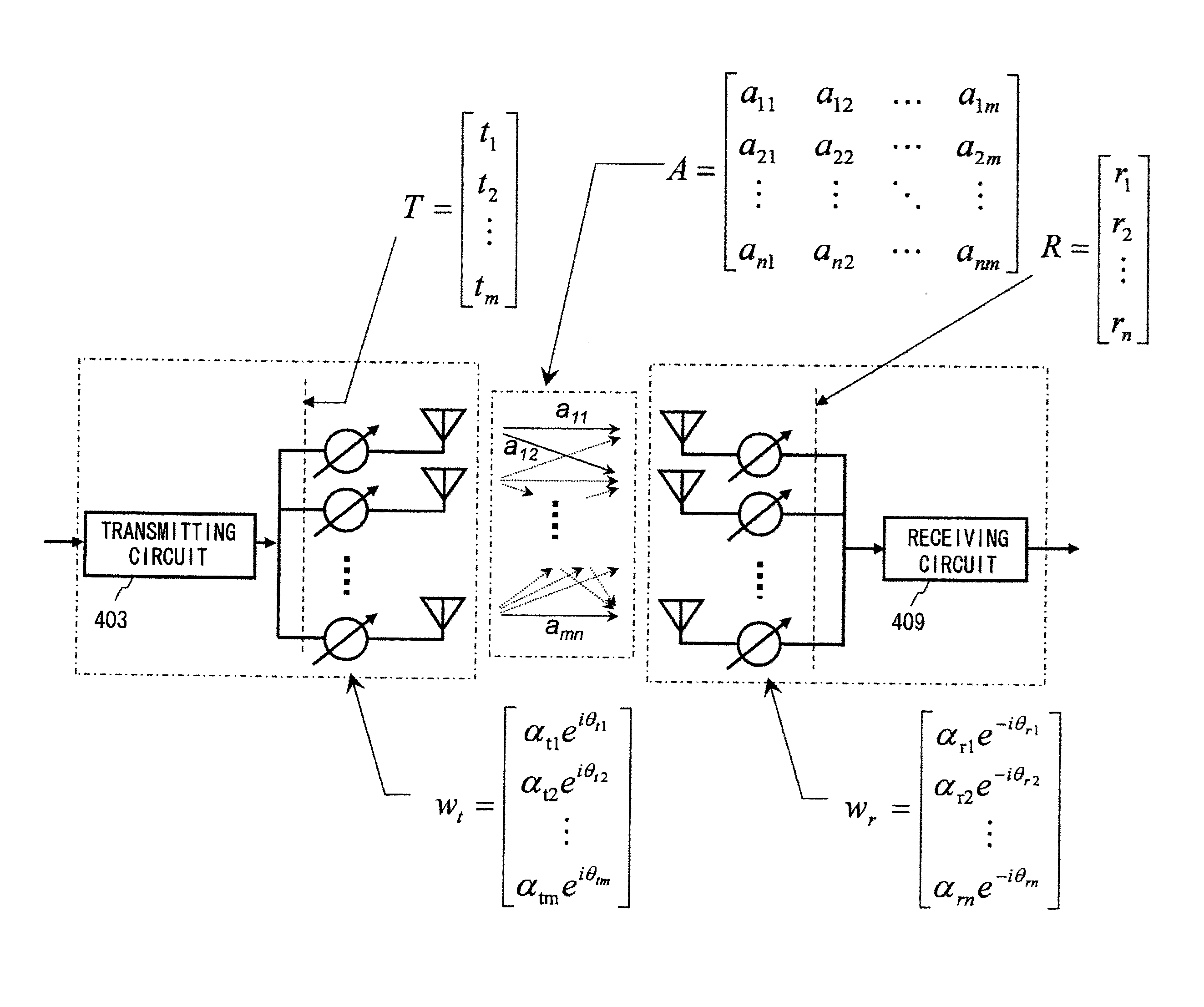
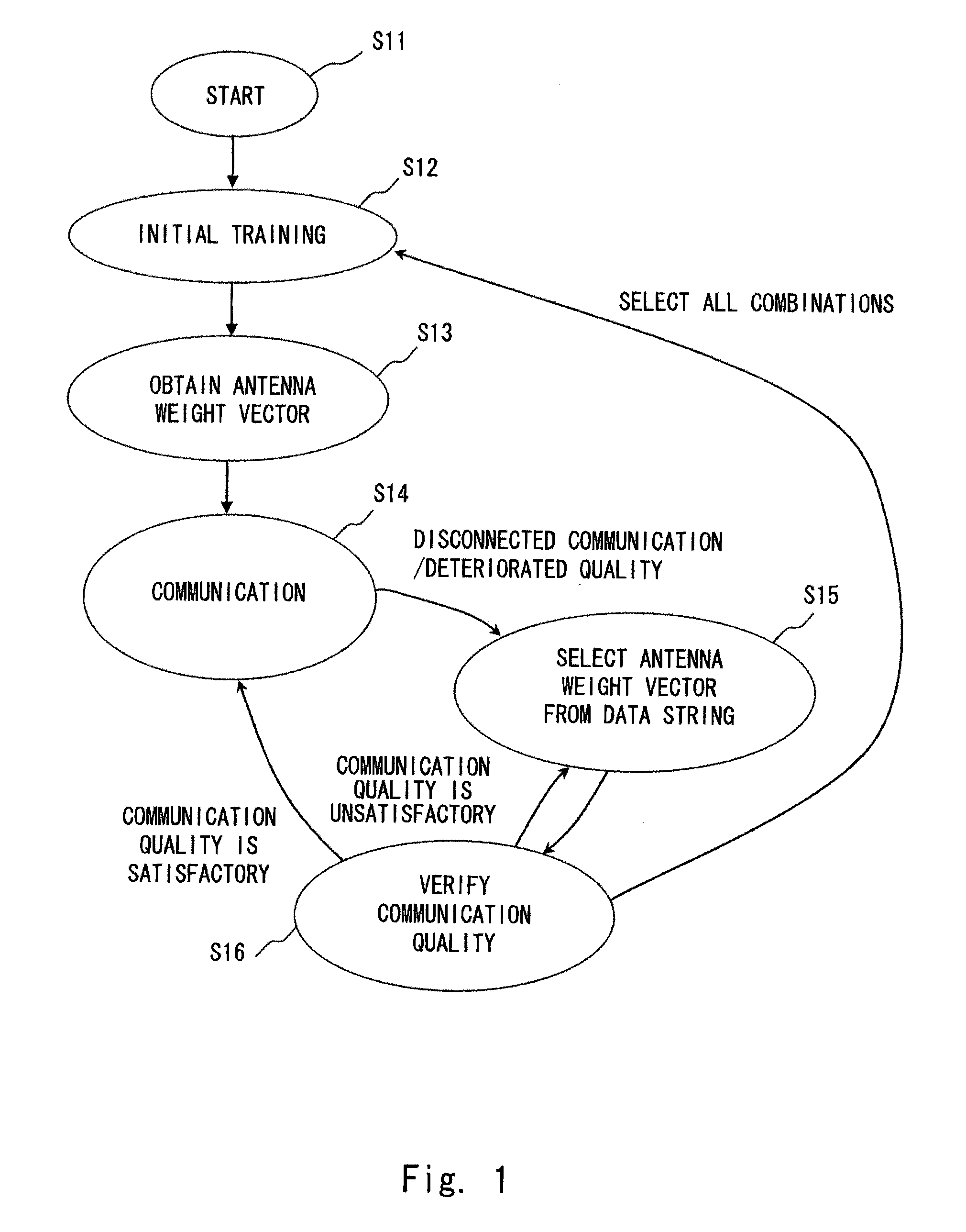
[0043]A first exemplary embodiment of the present invention is explained with reference to a transition diagram shown in FIG. 1. Note that the wireless communication system in accordance with this exemplary embodiment may employ a similar configuration to that shown in FIG. 4. In S12, a transmitter 401 and a receiver 402 perform an initial training in order to optimize amplitude / phase variable circuits 404-1 to 404-m and 410-1 to 410-n provided in the transmitter 401 and receiver 402. In S13, a processing / arithmetic circuit 406 or 412, or both of them in cooperation calculate a plurality of candidate antenna weight vectors. The calculation method for the plurality of candidate antenna weight vectors in S13 is described later. The obtained plurality of candidate antenna weight vectors are recorded as a data string in storage circuits 408 and 414.

[0044]In S14, one candidate is selected from the plurality of candidate phase combination obtained in S13 to perform communication. In this ...

second exemplary embodiment

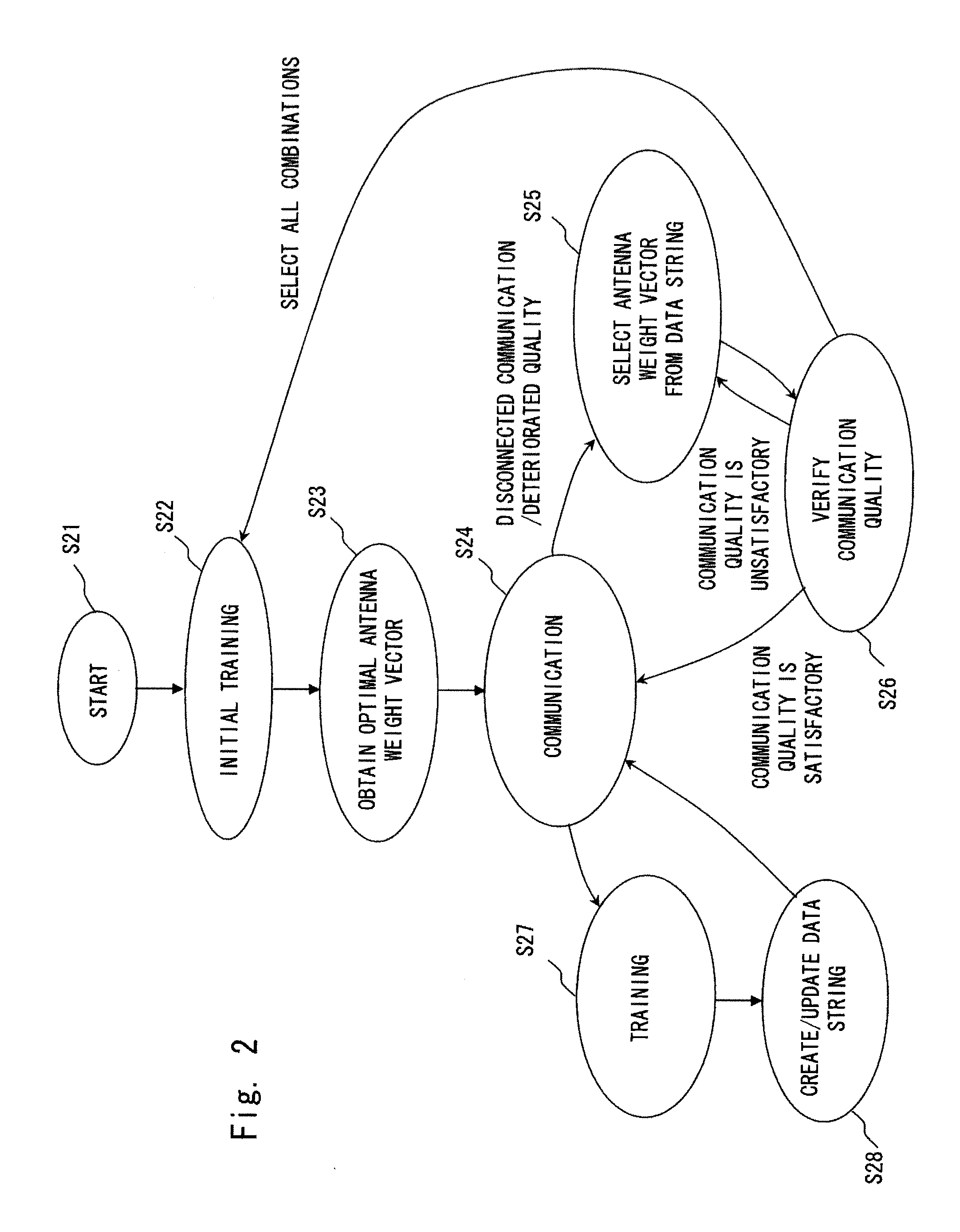
[0072]A second exemplary embodiment of the present invention is explained with reference to a transition diagram shown in FIG. 2. Note that the wireless communication system in accordance with this exemplary embodiment may employ a similar configuration to that shown in FIG. 4. Each state from S21 to S26 shown in FIG. 2 as well as their transition conditions are similar to those described in the first exemplary embodiment and shown as S11 to S16 in FIG. 1. Therefore, detailed explanations of S21 to S26 are omitted.

[0073]In S27 of FIG. 2, the processing state is changed from the communication continuation state (S24) to perform an additional second training. The second training may be performed at regular intervals, or may be performed during idle times in which no data is transmitted / received.

[0074]In S28, the processing / arithmetic circuit 406 or 412, or both of them in cooperation re-calculate a plurality of candidate antenna weight vectors. The processing / arithmetic circuits 406 a...

third exemplary embodiment

[0076]A third exemplary embodiment of the present invention is explained with reference to a transition diagram shown in FIG. 3. The wireless communication system in accordance with this exemplary embodiment may employ a similar configuration to that shown in FIG. 4. Further, the wireless communication system in accordance with third exemplary embodiment performs the same operations as those of the second exemplary embodiment. That is, each state from S31 to S38 shown in FIG. 3 as well as their transition conditions are similar to those described in the second exemplary embodiment and shown as S21 to S28 in FIG. 2. Therefore, detailed explanations of S31 to S38 are omitted.

[0077]In this exemplary embodiment, when deterioration in the communication quality such as disconnected communication or the like occurs, the next candidate antenna weight vector is selected from the plurality of candidates recorded in the database (S35) and a fine adjustment is performed in that state (S39). Thi...


PUM


Abstract

A channel response matrix is obtained by performing a training process between a transmitter 401 and a receiver 402 to obtain optimal signal phases of the antenna array. Next, a singular-value decomposition (SVD) process is performed to decompose the channel response matrix into a correlation matrix and eigenvalues. Next, a diagonal matrix having square roots of the eigenvalues as its components is obtained. Next, all but one of diagonal components included in the diagonal matrix are replaced with zeros, and optimal setting of the amplitudes and phases of signals to be applied to the antenna array (antenna weight vector) for use in wireless communication between the transmitter and the receiver is obtained based on a channel response matrix that is reconstructed by using the component-replaced diagonal matrix. In this way, when wireless communication is implemented by performing beam forming, the time necessary to find and set a beam direction can be reduced.

Description

TECHNICAL FIELD[0001]The present invention relates to a technical field of wireless communication in which wireless communication is implemented by using radio beams that are set based on the communication quality.BACKGROUND ART[0002]In recent years, wireless devices using wide-band millimeter waves (30 GHz to 300 GHz) have become widespread. The millimeter-wave radio technology has been expected to be especially applicable to Gigabit-class high-rate radio data communication such as radio transmission of high-resolution images (for example, see Non-patent literatures 1 and 2).[0003]However, the millimeter waves, which have high frequencies, have a high rectilinear propagation property, and thus raising a problem when radio transmission is to be implemented indoors. In addition to having the high rectilinear propagation property, the millimeter-wave signals are significantly attenuated by a human body or other objects. Therefore, when a person stands between the transmitter and the r...

Claims


Application Information

Patent Timeline
Patent Type & Authority Applications(United States)
IPC IPC(8): H04B7/04
CPCH04B7/0617
Inventor MARUHASHI, KENICHIORIHASHI, NAOYUKIHOSOYA, KENICHI
Owner NEC CORP
Why Eureka
Try Eureka