
Microvessels, microparticles, and methods of manufacturing and using the same

a technology of micro-particles and micro-vessels, applied in the field of micro-particles, can solve the problems of image providing limited information, imagers or optical detectors cannot detect amplification from a side of the through, and the above method may have certain challenges or limitations, so as to facilitate the detection of optical characteristics

Active Publication Date: 2011-05-05
ILLUMINA INC
View PDF50 Cites 17 Cited by
  • Summary
  • Abstract
  • Description
  • Claims
  • Application Information

AI Technical Summary

Benefits of technology

[0010]In accordance with one embodiment, an encoded microvessel is provided that includes a microbody and a reservoir core that extends into the microbody. The microbody can be configured to separate a substance, such as a biological or chemical substance, in the reservoir core from an ambient environment that surrounds the microbody. The microbody can include a material that at least partially surrounds the reservoir core and facilitates detection of a characteristic of the substance within the reservoir core. Optionally, the material can be transparent so as to facilitate detection of an optical characteristic of a substance within the reservoir core. The microbody can have an identifiable code that is associated with the substance.
[0012]In yet another embodiment, a method of reading a plurality of encoded microvessels used in an assay for biological or chemical analysis is provided. The method can include providing a plurality of encoded microvessels. The microvessels can include a respective microbody and a reservoir core configured to hold a substance in the reservoir core. The microbody can include a material that surrounds the reservoir core and facilitates detection of a characteristic of the substance within the reservoir core. Optionally, the material can be transparent so as to facilitate detection of an optical characteristic of a substance within the reservoir core. The microbody can include an identifiable code associated with the substance. The method can also include determining the corresponding codes of the microvessels.
[0014]In another embodiment, an isolated microvessel is provided that includes an encoded microvessel having a microbody and a reservoir core. The microbody can be configured to separate a biological or chemical substance in the reservoir core from an ambient environment surrounding the microbody. The microbody can include a material that at least partially surrounds the reservoir core and facilitates detection of a characteristic of the substance within the reservoir core. Optionally, the material can be transparent so as to facilitate detection of an optical characteristic of a substance within the reservoir core. The microbody can include an identifiable code associated with the substance. The isolated microvessel can also include a compartment that is configured to separate the microvessel from an ambient environment surrounding the compartment.
[0015]In a further embodiment, a plurality of isolated microvessels is provided that includes a plurality of encoded microvessels. Each encoded microvessel can include a microbody and a reservoir core. The microbody can be configured to separate a biological or chemical substance in the reservoir core from an ambient environment surrounding the microbody. The microbody can include a material that at least partially surrounds the reservoir core and facilitates detection of a characteristic of the substance within the reservoir core. Optionally, the material can be transparent so as to facilitate detection of an optical characteristic of a substance within the reservoir core. The microbody of each microvessel can include an identifiable code that distinguishes individual microvessels of the plurality of encoded microvessels from each other. The plurality of isolated microvessels can also include a plurality of compartments. Each compartment can be configured to separate individual microvessels of the plurality of encoded microvessels from each other.

Problems solved by technology

However, the above method may have certain challenges or limitations.
Second, an imager or optical detector cannot detect amplification from a side of the through-hole but must face one of the plate surfaces in order to detect light emitting from the through-holes.
As such, in assays that include real-time imaging or in assays that are interested in diffusion properties of the reactants, the image may provide limited information.
Furthermore, the plate's size and shape limit or restrict the plate's use in systems where more sortable or transportable substrates are desired.
However, emulsion PCR has limited applications.
First, the aqueous micelles are difficult to individually identify and manipulate.
Second, the aqueous micelles have limited sizes and shapes and have a limited stability since the surface tension properties are determined by the composition of the aqueous solution.
As such, use of the emulsion PCR method is generally limited to situations when the composition of the aqueous solution forms stable aqueous micelles in the oil-surfactant mixture.
Accordingly, emulsion PCR may not be suitable for assays that desire bioreactors having certain sizes or shapes.
Third, after the aqueous micelles are formed in emulsion PCR, it may be difficult to manipulate or handle the aqueous micelles in a controlled manner.
For example, it may be difficult to add reagents or other chemicals incrementally to the aqueous micelles.
Furthermore, it may be difficult to add reagents or other chemicals selectively to certain aqueous micelles and not others.

Method used


Image

  • Microvessels, microparticles, and methods of manufacturing and using the same
  • Microvessels, microparticles, and methods of manufacturing and using the same
  • Microvessels, microparticles, and methods of manufacturing and using the same

Examples


Embodiment Construction

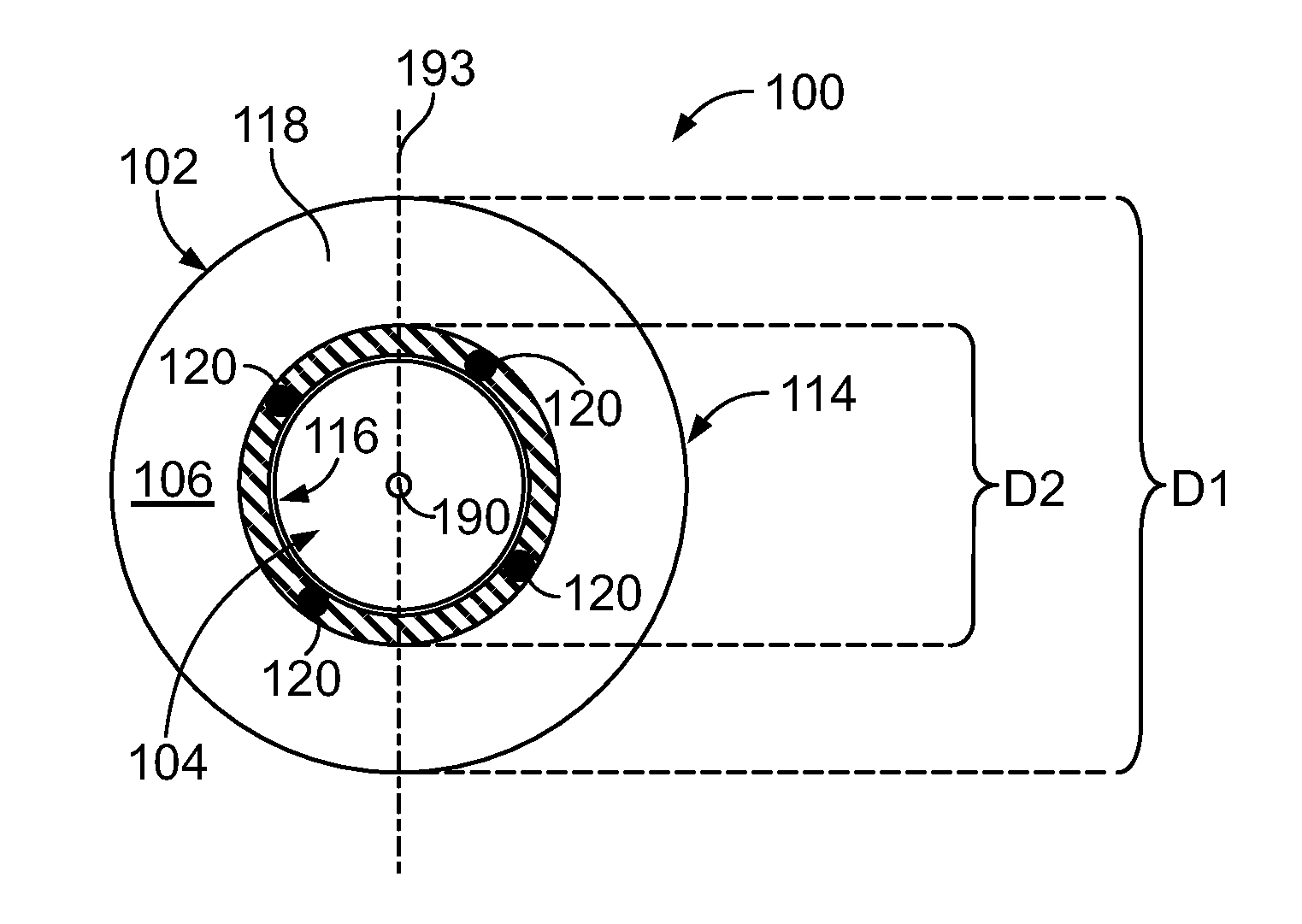
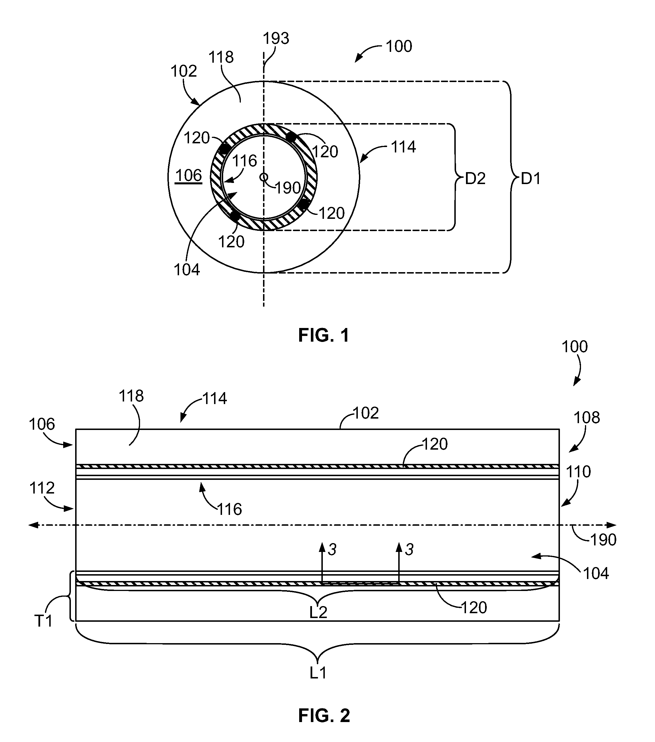
[0065]FIGS. 1 and 2 illustrate an exemplary microvessel 100 that may be formed in accordance with one embodiment. The microvessel 100 may include a microbody 102 having a reservoir core or cavity 104 where a substance, such as a biological or chemical substance (not shown), may be located. Embodiments described herein include microvessels that are configured to isolate or separate a substance from an ambient environment and / or other microvessels. In some embodiments, the microvessels may function as reactors that isolate or separate biological, chemical, or other substances within the reservoir cores from the ambient environment and compartmentalize reactions, such as chemical or biological reactions, therein. For example, microvessels may be used to amplify or sequence nucleic acids within the reservoir core. Accordingly, the microvessels may be referred to as microreactors (or bioreactors or chemical reactors). In particular embodiments, microvessels described herein may also be r...


PUM

PropertyMeasurementUnit
Concentrationaaaaaaaaaa
Volumeaaaaaaaaaa
Transparencyaaaaaaaaaa

Abstract

A method of reading a plurality of encoded microvessels used in an assay for biological or chemical analysis. The method can include providing a plurality of encoded microvessels. The microvessels can include a respective microbody and a reservoir core configured to hold a substance in the reservoir core. The microbody can include a material that surrounds the reservoir core and facilitates detection of a characteristic of the substance within the reservoir core. Optionally, the material can be transparent so as to facilitate detection of an optical characteristic of a substance within the reservoir core. The microbody can include an identifiable code associated with the substance. The method can also include determining the corresponding codes of the microvessels.

Description

CROSS-REFERENCES TO RELATED APPLICATIONS[0001]The present application claims the benefit of U.S. Provisional Application No. 61 / 256,582, filed Oct. 30, 2009 and entitled “Microvessels and Methods of Manufacturing and Using the Same,” which is incorporated by reference in its entirety.BACKGROUND OF THE INVENTION[0002]Embodiments of the present invention relate generally to microparticles and more particularly, to microvessels that separate substances, such as biological or chemical substances, from an ambient environment.[0003]Various protocols in biological or chemical research involve performing a large number of controlled chemical reactions within solutions or mixtures that are isolated from each other and / or from an ambient environment. Such isolated solutions or mixtures (i.e., reaction volumes) may be formed in assays by using test tubes, microcentrifuge tubes, and wells of microplates. For example, in multiplex assays, an unknown analyte having an identifiable label (e.g., fl...

Claims


Application Information

Patent Timeline
IPC IPC(8): C40B30/10C40B40/00
CPCB01J2219/00306B01J19/0046B01J2219/0052B01J2219/00524B01J2219/00545B01J2219/00576B01J2219/00585B01J2219/00673B01J2219/00702B01J2219/0072B01L3/502761B01L3/5082B01L3/50857B01L3/5088B01L3/545C40B20/04G01N21/253G01N21/6452G01N21/01G01N35/00732G01N33/50B01J2219/00596B01J2219/00511
Inventor MOON, JOHN A.BOWEN, M. SHANESMITH, RYAN C.PERBOST, MICHELLEBL, MICHALMODIANO, STEVEN H.
Owner ILLUMINA INC
Learn More