Transcranial magnetic stimulation by enhanced magnetic field perturbations

a technology of enhanced magnetic field and transcranial magnetic stimulation, which is applied in the field of transcranial magnetic stimulation, can solve the problems of difficult prediction or model, complex current path, and difficulty in estimating the efficiency of stimulation for any given position and power of tms electromagnet, and achieve enhanced changing magnetic field (db/dt), enhanced local stimulation, and enhanced the effect of magnetic field

Inactive Publication Date: 2011-05-05
CERVEL NEUROTECH
View PDF3 Cites 43 Cited by
  • Summary
  • Abstract
  • Description
  • Claims
  • Application Information

AI Technical Summary

Benefits of technology

[0013]Described herein are devices, systems and methods for Transcranial Magnetic Stimulation involving the use of one or more magnetic coils, pulsed together or serially. The magnetic coils are moved in a perturbing motion in the x, y, and / or z motion, so that the magnetic field emitted by the TMS electromagnet and the consequently stimulated electrical fields are changed quickly enough to allow perturbation of the local electrical environment at the target to facilitate local stimulation. The enhanced changing magnetic field (dB / dt) resulting from the perturbing motion many enhance the effect of the magnetic field on the target neural structure(s). This effect of the perturbing motion of the TMS electromagnet can be achieved with any TMS electromagnet, irrespective of coil shape, type or higher-order configuration within an array of electromagnets, as long as they can physically be moved in a manner consistent with this invention.

Problems solved by technology

Thus, bending nerve fibers may be more susceptible to TMS effects than straight fibers.
Because of the irregular shape of the brain, and the often tortuous pathways of various neurons in the brain, the resulting current path is complex and may be difficult to predict or model.
Thus it is often difficult to estimate the efficiency of stimulation for any given position and power of the TMS electromagnet.
However, in this example, field perturbations within each single pulse are typically limited to the energy and the time course of the signal produced by the pulse generation unit (PGU) output.

Method used


Image

  • Transcranial magnetic stimulation by enhanced magnetic field perturbations
  • Transcranial magnetic stimulation by enhanced magnetic field perturbations
  • Transcranial magnetic stimulation by enhanced magnetic field perturbations

Examples


Embodiment Construction

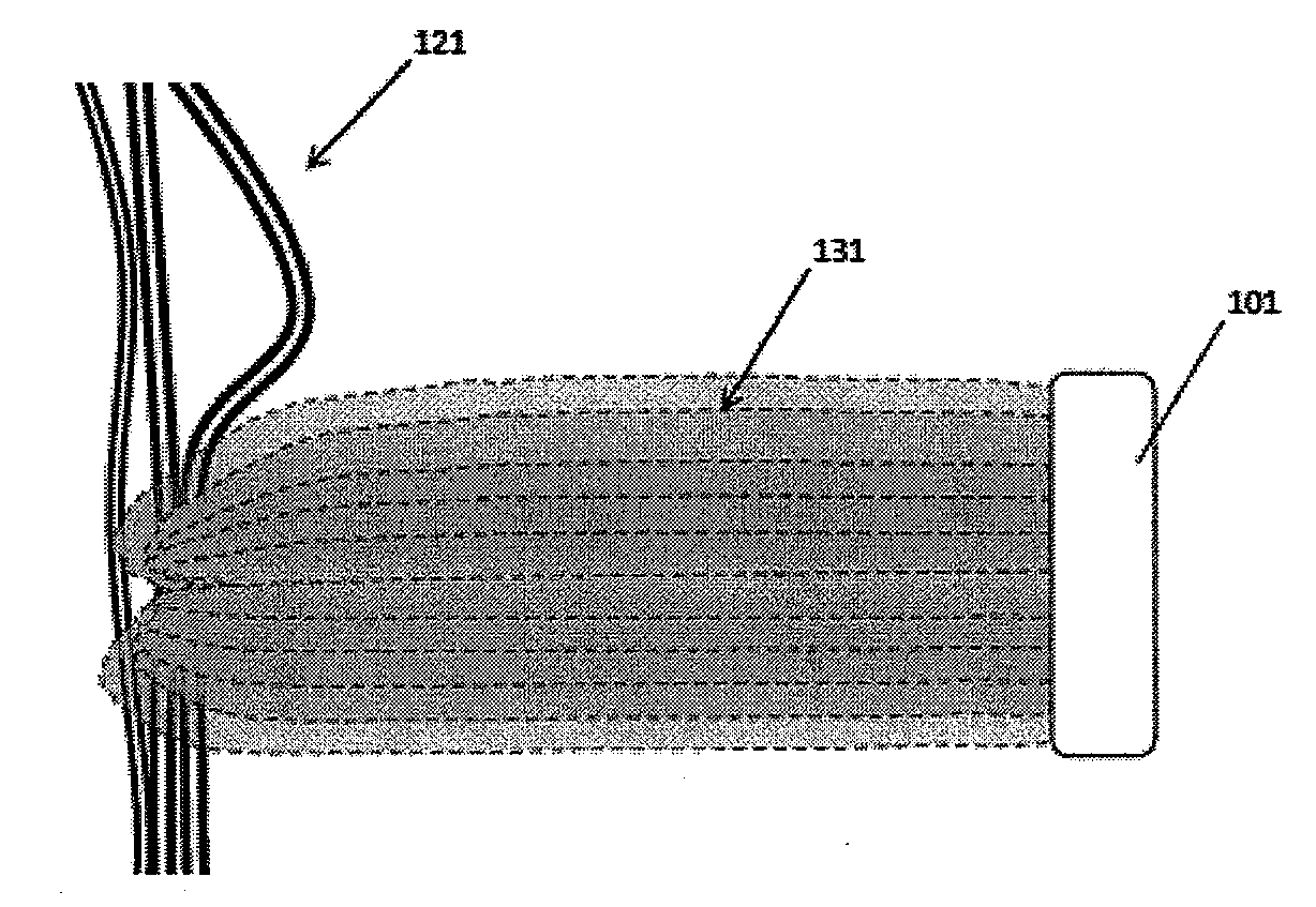
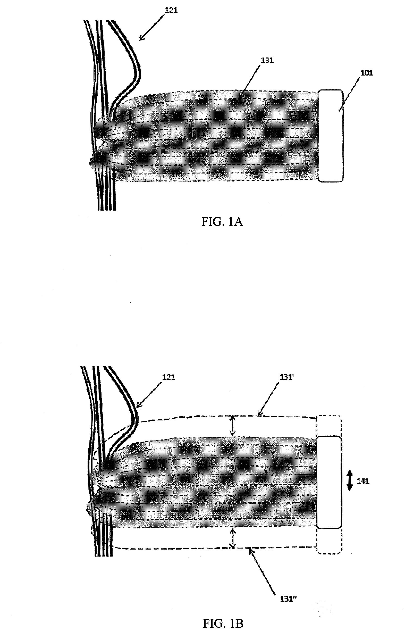
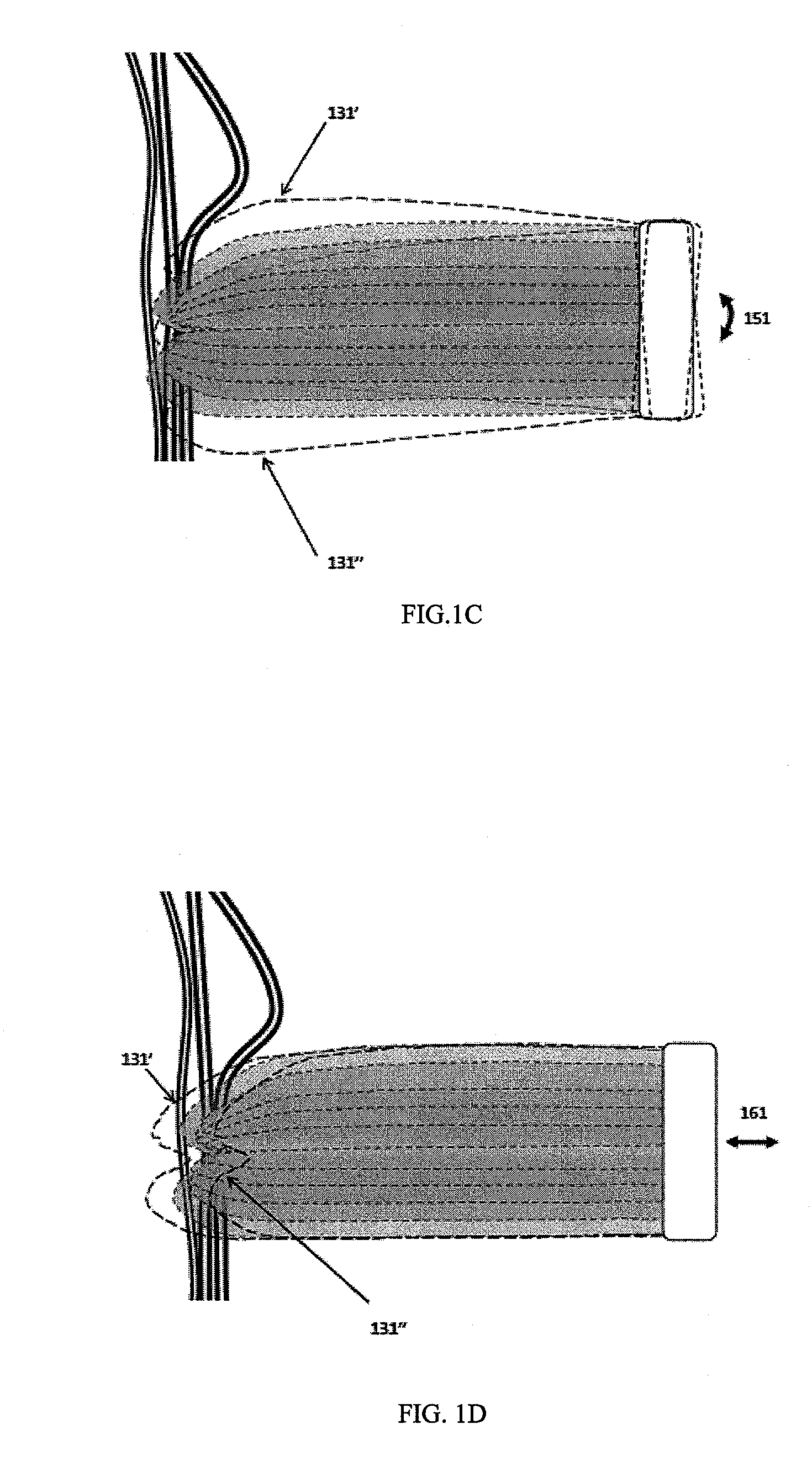
[0039]The devices, systems and methods described herein are intended to enhance the magnetic perturbation of a neuronal (e.g., brain) target during Transcranial Magnetic Stimulation (TMS), thereby enhancing the induced current in the target. In general, these devices, systems and methods enhance the magnetic perturbation (e.g., dB / dt) of the target by mechanically moving a TMS electromagnet (e.g., coil) at a frequency of greater than 1 kHz.

[0040]The principles of the present invention do not depend on the coil shape, type or higher-order configuration within an array of electromagnets, as long as electromagnetic field generated has a shaped component that is directed towards the target. Accordingly, the figures and illustrations described below depict generic electromagnet shapes, though it is to be understood that any appropriate configuration may be used. One example of a TMS electromagnet configuration is a figure-eight, double coil, including those sold by Medtronic (e.g., MC-B7...


PUM


Abstract

Described herein are devices, systems and methods to enhance the magnetic perturbation of a neuronal (e.g., brain) target during Transcranial Magnetic Stimulation (TMS), thereby enhancing the induced current in the target. In general, these devices, systems and methods enhance the magnetic perturbation (dB/dt) of the target by mechanically moving a TMS electromagnet (e.g. coil) at a frequency of greater than 1 kHz.

Description

CROSS REFERENCE TO RELATED APPLICATIONS[0001]This patent claims priority to U.S. Provisional Patent Application Ser. No. 61 / 055,463, filed on May 23, 2008 and titled “PHYSICAL COIL MOVEMENT FOR ENHANCED MAGNETIC FIELD PERTURBATIONS”.[0002]This application may be related to U.S. Pat. No. 7,520,848 to Schneider et al.INCORPORATION BY REFERENCE[0003]All publications and patent applications mentioned in this specification are herein incorporated by reference in their entirety to the same extent as if each individual publication or patent application was specifically and individually indicated to be incorporated by reference.FIELD OF THE INVENTION[0004]The devices and methods described herein relate generally to the control of Transcranial Magnetic Stimulation (TMS). In particular, described herein are methods, devices and systems for TMS by precisely moving the TMS electromagnet(s) to enhance perturbations of neural tissue.BACKGROUND OF THE INVENTION[0005]Transcranial magnetic stimulati...

Claims


Application Information

Patent Timeline
Patent Type & Authority Applications(United States)
IPC IPC(8): A61N2/02A61N2/00
CPCA61N2/02A61N2/006
Inventor MISHELEVICH, DAVID J.SCHNEIDER, M. BRET
Owner CERVEL NEUROTECH
Why Eureka
Try Eureka