Multiple sensor system and method for mapping soil in three dimensions

a three-dimensional mapping and sensor system technology, applied in the direction of material analysis, instruments, and reradiation, can solve the problems of limiting the quantitative information about the soil properties that exist within the profile at each location, the number of soil samples needed to accurately map the soil variability, and the challenge of soil scientists and soil classifiers

Active Publication Date: 2011-05-05
VERIS TECH
View PDF16 Cites 79 Cited by
  • Summary
  • Abstract
  • Description
  • Claims
  • Application Information

AI Technical Summary

Benefits of technology

The present invention provides a multi-sensor system capable of rapidly measuring diffuse reflectance of soil, soil conductivity, and other soil properties in situ, in three dimensions. The system includes a tractor-drawn implement containing a sensor shank used for X-Y axis measurements, a hydraulic probe implement containing a sensor probe for −Z axis measurements, and a set of visible and near-infrared spectrometers, controls, and firmware that are shared by each implement. In addition to the optical sensors, both implements include soil electrical conductivity sensors. The probe implement incorporates a sensor that measures insertion force, and the shank implement includes a soil temperature sensor. These combinations of sensors

Problems solved by technology

Mapping soil properties precisely, especially identifying differences hidden within the soil profile, has proven challenging for soil scientists and soil classifiers.
While GPS technology provides precise positional information, quantitative information about the soil properties that exist within the profile at each location remains a limiting factor.
The number of soil samples needed to accurately map soil variability is impractical using conventional sampling and analysis methods.
One of the important issues involving in situ soil measurements relates to reducing atmospheric carbon by incre

Method used


Image

  • Multiple sensor system and method for mapping soil in three dimensions
  • Multiple sensor system and method for mapping soil in three dimensions
  • Multiple sensor system and method for mapping soil in three dimensions

Examples


Embodiment Construction

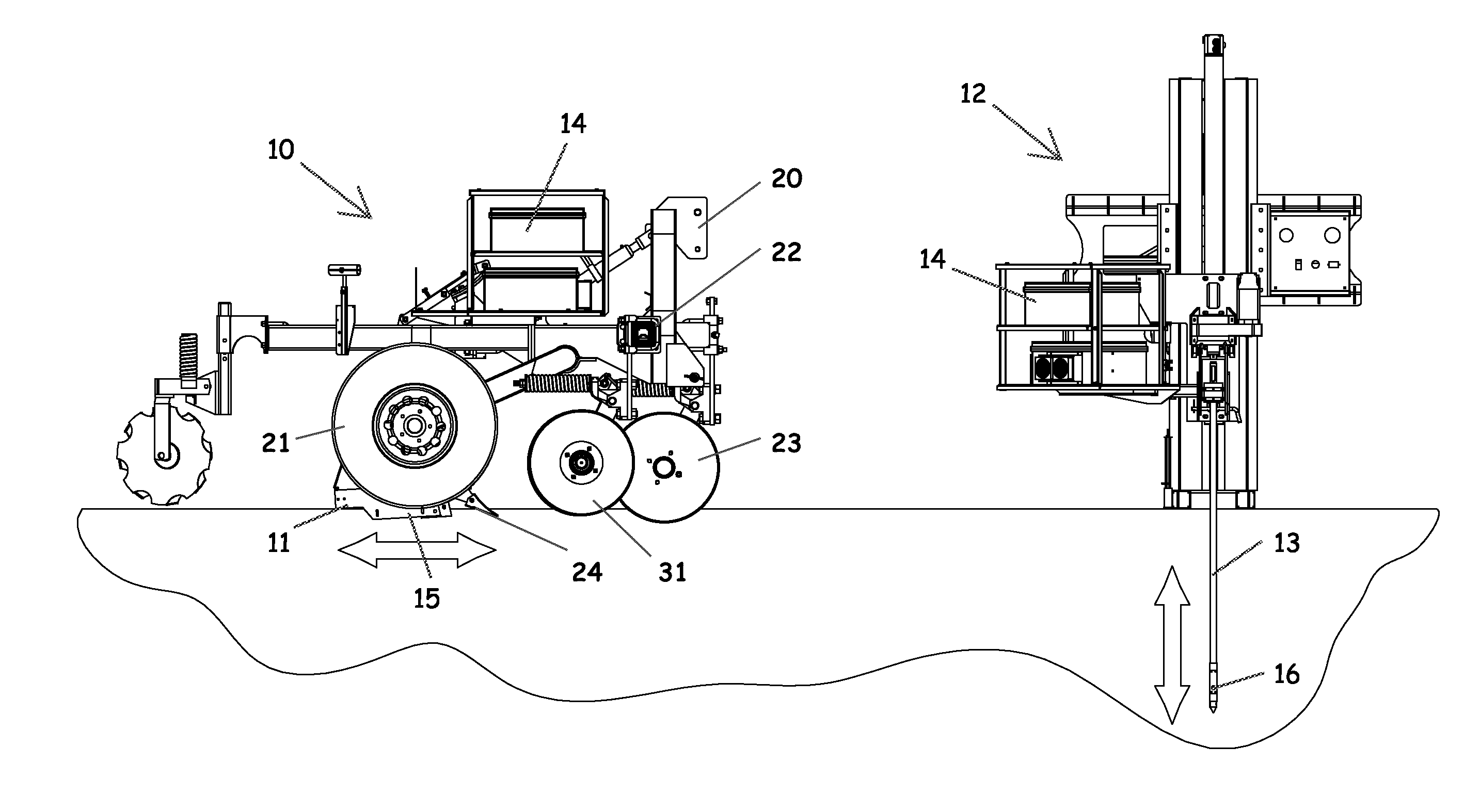
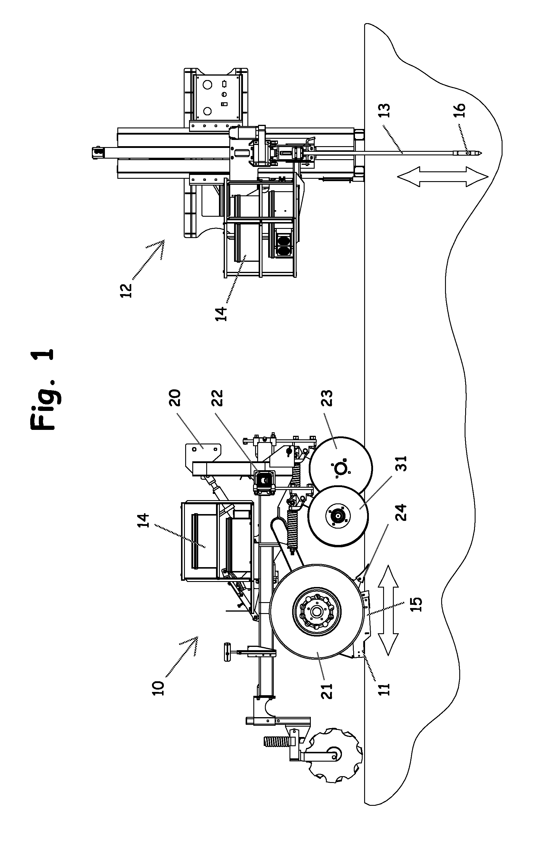
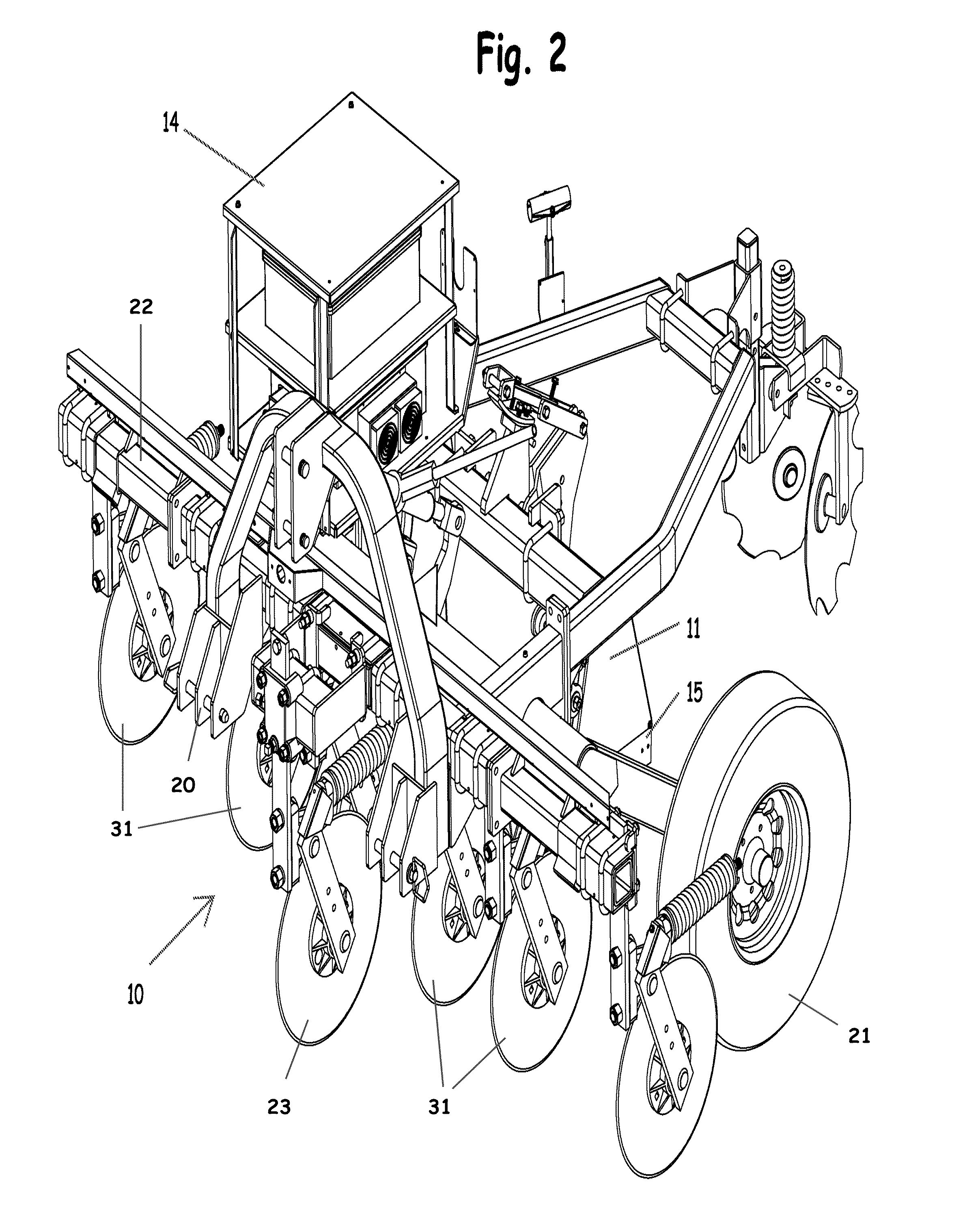
A mobile soil mapping system and method for mapping soils within a field in three dimensions using multiple sensors according to the present invention will now be described in detail with reference to FIGS. 1 to 11 of the accompanying drawings.

The soil mapping system of the present invention includes a tractor drawn implement 10 containing a sensor shank assembly 11 used for X-Y axis measurements, a hydraulic probe implement 12 containing a sensor probe 13 for −Z axis measurements, and a set of visible and near-infrared spectrometers 14, controls, and firmware that are shared by each implement 10, 12.

The shank implement 10 has a reflectance module 15 carried by the sensor shank assembly 11 to collect spectral data of the soil in a generally horizontal X-Y plane. The shank implement 10 also includes a shallow (e.g., 12 inch depth) soil electrical conductivity sensor 31, a deep (e.g., 30 inch depth) soil electrical conductivity sensor 32, and a soil temperature sensor 33. These compon...


PUM


Abstract

A multi-sensor system rapidly measures diffuse reflectance of soil, soil conductivity, and other soil properties in situ, in three dimensions. The system includes a tractor-drawn implement containing a sensor shank used for X-Y axis measurements, a hydraulic probe implement containing a sensor probe for −Z axis measurements, and a set of visible and near-infrared spectrometers, controls, and firmware that are shared by each implement. Both implements include optical sensors and soil electrical conductivity sensors. The probe implement incorporates a sensor that measures insertion force, and the shank implement includes a soil temperature sensor. These combinations of sensors are used to calibrate the system and to characterize the soil properties within a field or area. Geo-referenced soil measurements are collected with the shank implement to identify optimal locations for conducting sensor probe insertions. The probe implement is then used for sensor probing and for collecting soil core samples for lab analysis.

Description

BACKGROUND OF THE INVENTION1. Field of the InventionThe present invention relates generally to methods and devices for analyzing and mapping soil properties within a field. In particular, the present invention relates to methods and devices for mapping soils within a field in three dimensions using multiple sensors.2. Description of the Related ArtMapping soil properties precisely, especially identifying differences hidden within the soil profile, has proven challenging for soil scientists and soil classifiers. While GPS technology provides precise positional information, quantitative information about the soil properties that exist within the profile at each location remains a limiting factor. The number of soil samples needed to accurately map soil variability is impractical using conventional sampling and analysis methods.One of the important issues involving in situ soil measurements relates to reducing atmospheric carbon by increasing the amount of carbon stored in the soil. Fo...

Claims


Application Information

Patent Timeline
IPC IPC(8): G01V3/38
CPCG01N21/359G01N21/3563G01V11/00G01N21/8507
Inventor CHRISTY, COLINDRUMMOND, PAULKWEON, GIYOUNGMAXTON, CHASEDREILING, KENTONJENSEN, KYLELUND, ERIC
Owner VERIS TECH
Why Eureka
Try Eureka