Mobile soil optical mapping system

an optical mapping and mobile technology, applied in the field of mobile soil optical mapping system, can solve the problems of reducing the ability to collect such images, neither of these were fully commercialized, and relating the temporal variations to fundamental productivity zones, and achieve the effect of preventing erosion

Active Publication Date: 2017-08-29
VERIS TECH
View PDF18 Cites 31 Cited by
  • Summary
  • Abstract
  • Description
  • Claims
  • Application Information

AI Technical Summary

Benefits of technology

[0010]A soil mapping system for collecting and mapping soil reflectance data in a field includes an implement having a row unit with a furrow opener for creating a furrow and an optical module. The optical module is arranged to collect soil reflectance data at a predetermined depth within the furrow as the implement traverses a field. An opening coulter and a pair of trash clearing disks can be used to clear residue and cut a slice in front of the furrow opener. The furrow opener in one embodiment comprises two disks operating at a slight angle relative to the direction of travel to form a V-shaped slot in t...

Problems solved by technology

There have been some uses of bare soil photographs where the darker areas were correlated with higher organic matter levels, but with the increased use of conservation tillage and no-till farming, the ability to collect such images has diminished.
Due to several limitations in their designs, neither of these was fully commercialized.
Yield maps produced by combine yield monitors and remote crop imagery both show annual crop differences, but relating those temporal variations to fundamental productivity zones ...

Method used


Image

  • Mobile soil optical mapping system
  • Mobile soil optical mapping system
  • Mobile soil optical mapping system

Examples


Embodiment Construction

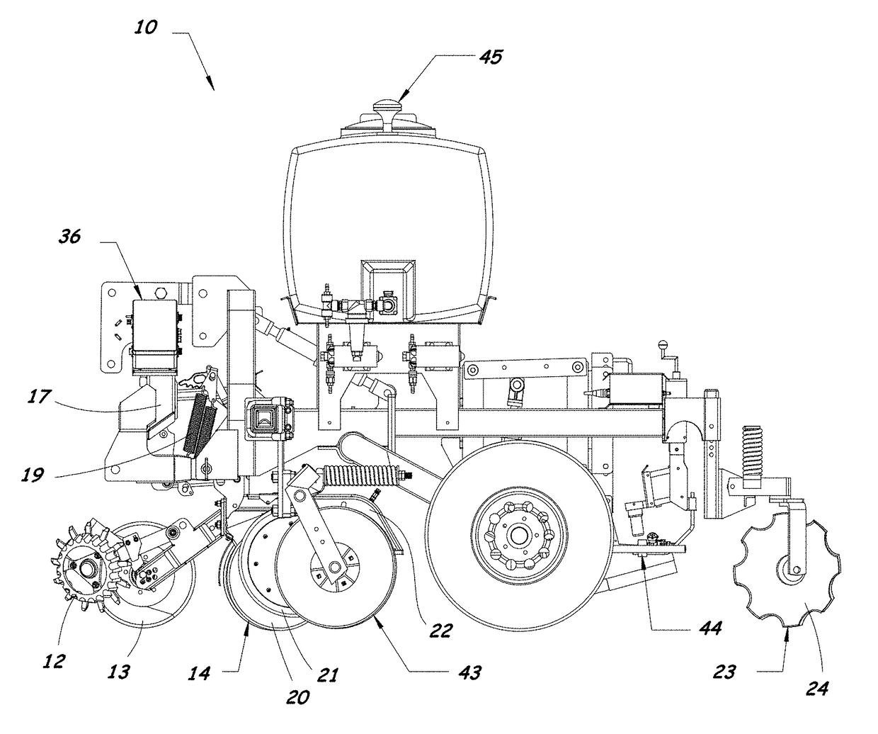
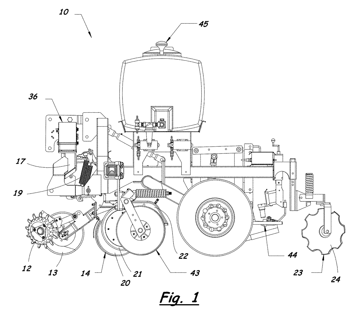
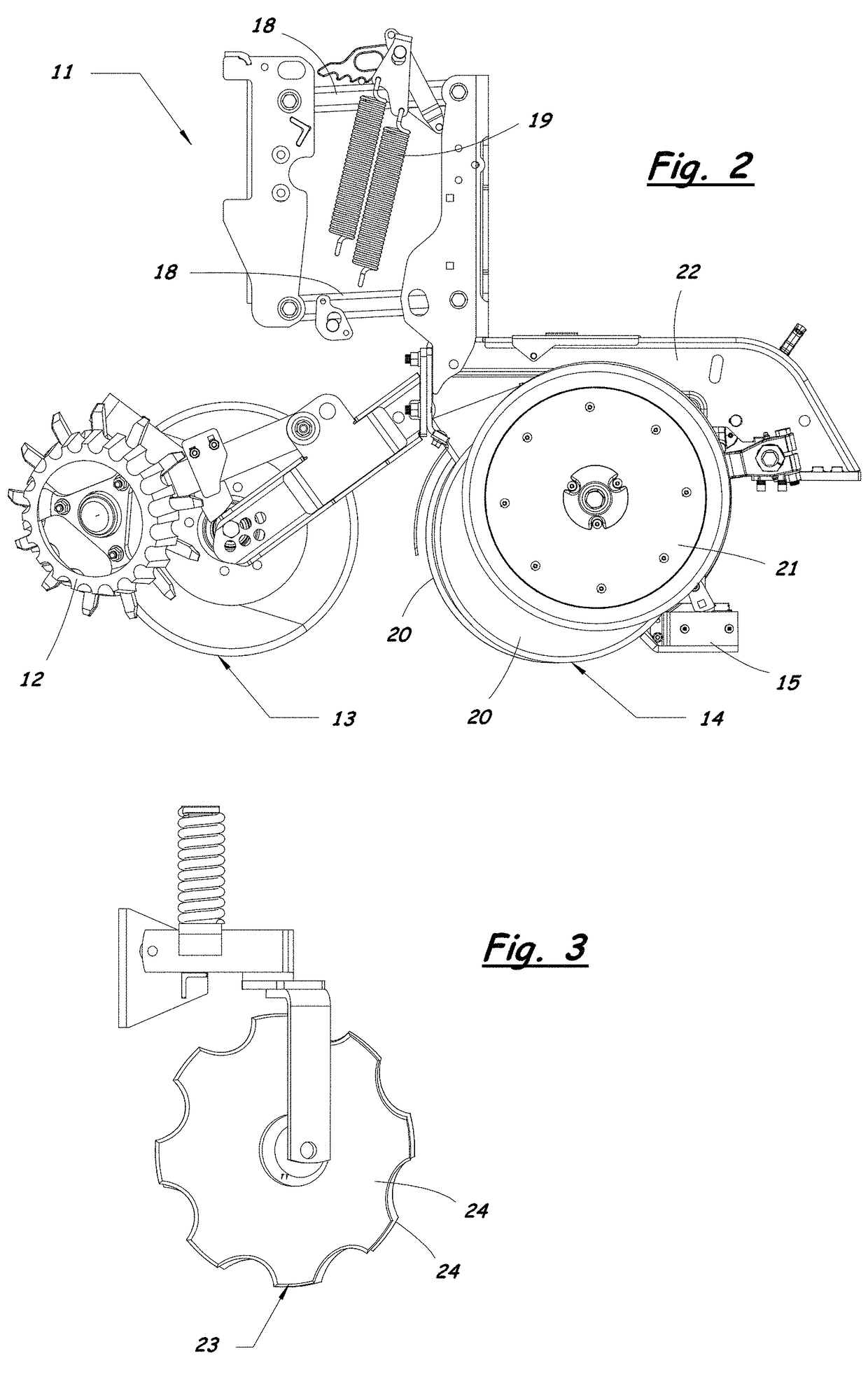
[0030]A mobile soil mapping system for collecting on-the-go reflectance measurements of soil in a field according to the present invention will now be described in detail with reference to FIGS. 1 to 13 of the accompanying drawings.

[0031]The primary objective of the present invention is to collect on-the-go optical measurements and correlate the data with soil organic matter levels. The soil mapping system described herein minimizes interferences from soil moisture and other sources of error through its mechanical, electronic, and data processing innovations.

[0032]Collecting high-quality optical measurements of soil in situ requires preparing the soil scene so the sensor will have an ideal view of the soil. This is accomplished in part by maintaining a consistent depth in the soil. The consistent depth is important because simple optical devices have difficulty differentiating soil moisture from organic matter, and soil moisture varies much more widely with depth than does organic m...


PUM


Abstract

A soil mapping system for collecting and mapping soil reflectance data in a field includes an implement having a furrow opener for creating a furrow and an optical module. The optical module is arranged to collect soil reflectance data at a predetermined depth within the furrow as the implement traverses a field. The optical module includes two monochromatic light sources, a window arranged to press against the soil, and a photodiode for receiving light reflected back from the soil through the window. The two light sources have different wavelengths and are modulated at different frequencies. The photodiode provides a modulated voltage output signal that contains reflectance data from both of the light sources. Additional measurement devices are carried by the implement for collecting additional soil property data, such as electrical conductivity, pH, and elevation, which can be used together with the optical data to determine variations in soil organic matter.

Description

RELATED APPLICATIONS[0001]This application claims priority of U.S. Provisional Application No. 61 / 394,740 filed on Oct. 19, 2010. This application is a continuation-in-part of U.S. application Ser. No. 12 / 253,594 filed on Oct. 17, 2008, now U.S. Pat. No. 8,204,689, which claims priority of U.S. Provisional Application No. 60 / 982,395 filed on Oct. 24, 2007. The entire contents of these prior applications are incorporated herein by reference.BACKGROUND OF THE INVENTION[0002]Field of the Invention[0003]The present invention relates generally to methods and devices for analyzing and mapping soil properties within a field. In particular, the present invention relates to methods and devices for collecting and mapping soil reflectance data on-the-go.[0004]Description of the Related Art[0005]Variations in soil properties can be detected, even with the human eye, based on differences in light reflectance. Darker soils contain higher levels of moisture or organic matter than light-colored soi...

Claims


Application Information

Patent Timeline
IPC IPC(8): G01V3/38G01N31/00A01B79/00G01S17/89G01N21/31G01N21/3563
CPCA01B79/005G01S17/89G01N21/31G01N21/3563A01C21/007G01N21/15G01N21/276G01N21/359G01N2201/0625G01V8/02
Inventor MAXTON, CHASEDRUMMOND, PAULLUND, ERICJENSEN, KYLE
Owner VERIS TECH
Why Eureka
Try Eureka