Hierarchical Reconfigurable Computer Architecture

a computer architecture and hierarchy technology, applied in the field of computer architecture, can solve the problems of inability to meet the high processing power requirements of modern designs, the simd architecture having a central context memory is not suitable for irregular algorithms, and the scheduling of operations within the cells is difficult to control

Active Publication Date: 2011-05-05
STMICROELECTRONICS SRL
View PDF14 Cites 47 Cited by
  • Summary
  • Abstract
  • Description
  • Claims
  • Application Information

AI Technical Summary

Benefits of technology

[0016]According to a further aspect of the present invention there is provided a method of mapping a required task onto the physical resources of a reconfigurable hierarchical computer architecture having N levels, where N is an integer value greater than one, a first level comprising a cluster comprising a plurality of interconnected computing nodes each comprising a functional unit, and a second lev

Problems solved by technology

FPGAs (Field Programmable Gate Arrays) are an example of a reconfigurable architecture that operates at bit level, and uses lookup tables, but is unable to meet high processing power requirements of modern designs.
Due to the design of the hardware in each cell, scheduling of operations within the cells is hard to control.
The SIMD architecture having a central context memory is not suitable for irregular algorithms such as those used for deblocking filters.
The array structure of the reconfigurable cells as well as the column and row interconnections between the cells is limiting for some requirements, and also reduces the scalability of the hardware as linear enlargement or reduction in size of the hardware is difficult.
A disadvantage of the DRESC compiler is that by performing mapping and scheduling as two separate steps the compiler is slow and inefficient.
Furthermore, this compiler is not able to process large applications due to complexity levels that grow exponentially.
When the complexity of the architecture increases, the execution time will explod

Method used


Image

  • Hierarchical Reconfigurable Computer Architecture
  • Hierarchical Reconfigurable Computer Architecture
  • Hierarchical Reconfigurable Computer Architecture

Examples


Embodiment Construction

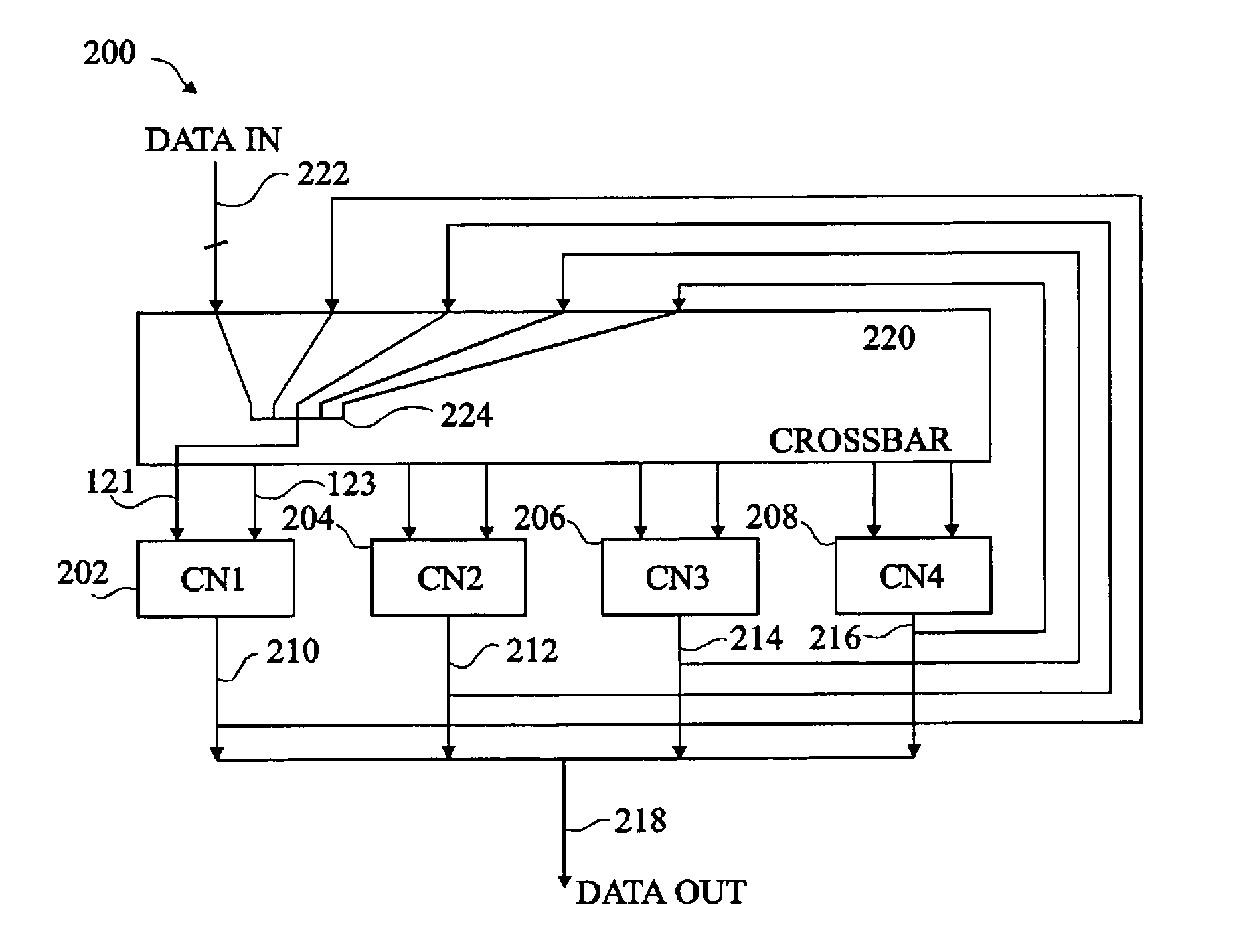
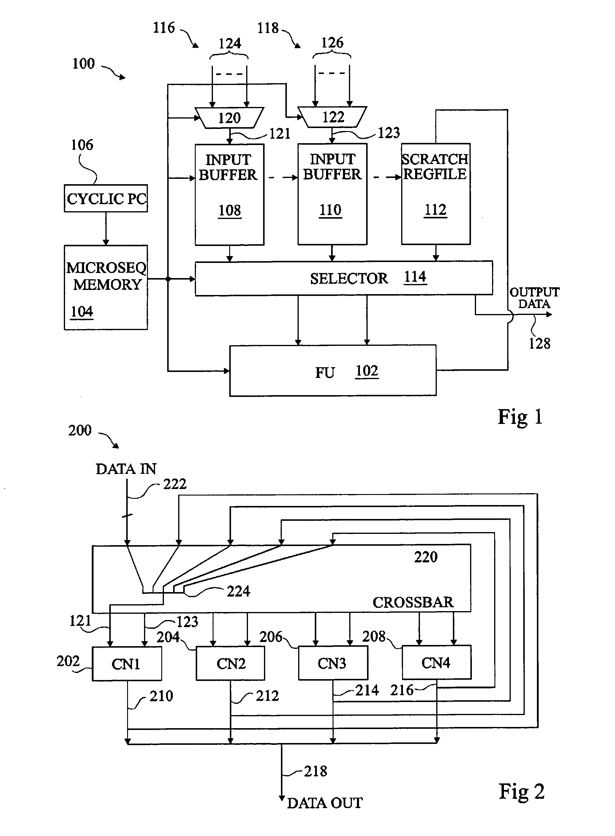
[0032]FIG. 1 illustrates a computing node 100. CN 100 comprises a functional unit 102, which is for example an arithmetic logic unit (ALU), and is capable of performing an operation on one or more inputs and providing an output. The operation performed by the functional unit 102 is controlled by a microsequence memory 104 connected to the functional unit, which stores instructions to be executed sequentially. A cyclic program count (PC) 106 is connected to the microsequence memory. First and second input buffers 108 and 110 and a scratch register file 112 provide inputs to the functional unit 102. Input buffers 108 and 110 each store for example 16 bits of data (one word), whilst the scratch register file 112 stores for example 64 bits of data (four words). The output of a functional unit is connected to the scratch register file 112, such that the output of the functional unit 102 maybe selected for input to the functional unit 102 on a subsequent cycle. The output of each input bu...


PUM


Abstract

A reconfigurable hierarchical computer architecture having N levels, where N is an integer value greater than one, wherein said N levels include a first level including a first computation block including a first data input, a first data output and a plurality of computing nodes interconnected by a first connecting mechanism, each computing node including an input port, a functional unit and an output port, the first connecting mechanism capable of connecting each output port to the input port of each other computing node; and a second level including a second computation block including a second data input, a second data output and a plurality of the first computation blocks interconnected by a second connecting means for selectively connecting the first data output of each of the first computation blocks and the second data input to each of the first data inputs and for selectively connecting each of the first data outputs to the second data output.

Description

FIELD OF THE INVENTION[0001]The present invention relates to a computer architecture and a method of mapping operations to the architecture. In particular the present invention relates to a hierarchical reconfigurable computer architecture.BACKGROUND OF THE INVENTION[0002]The complexity of digital electronic products is increasing rapidly, but at the same time electronic product producers wish to reduce the time to market of their products, and to lower costs. Much of the time associated with bringing a product to market is spent in validating and testing hardware implementations.[0003]Reconfigurable architectures provide a means of reducing the time to market by allowing designers to postpone commitment to a certain design until after silicon fabrication. Furthermore, updated designs can be loaded during the lifetime of a device to perform new functionality not envisaged at the time of first marketing the product. FPGAs (Field Programmable Gate Arrays) are an example of a reconfigu...

Claims


Application Information

Patent Timeline
IPC IPC(8): G06F15/76G06F9/02G06F9/46
CPCG06F15/7867G06F15/803G06F15/17381G06F13/368G06F15/173G06F9/3885
Inventor CAMBONIE, JOEL
Owner STMICROELECTRONICS SRL
Why Eureka
Try Eureka