
Device for reducing frictional resistance of ship body

Active Publication Date: 2011-05-12
MITSUBISHI SHIPBUILDING CO LTD
View PDF6 Cites 0 Cited by
  • Summary
  • Abstract
  • Description
  • Claims
  • Application Information

AI Technical Summary

Benefits of technology

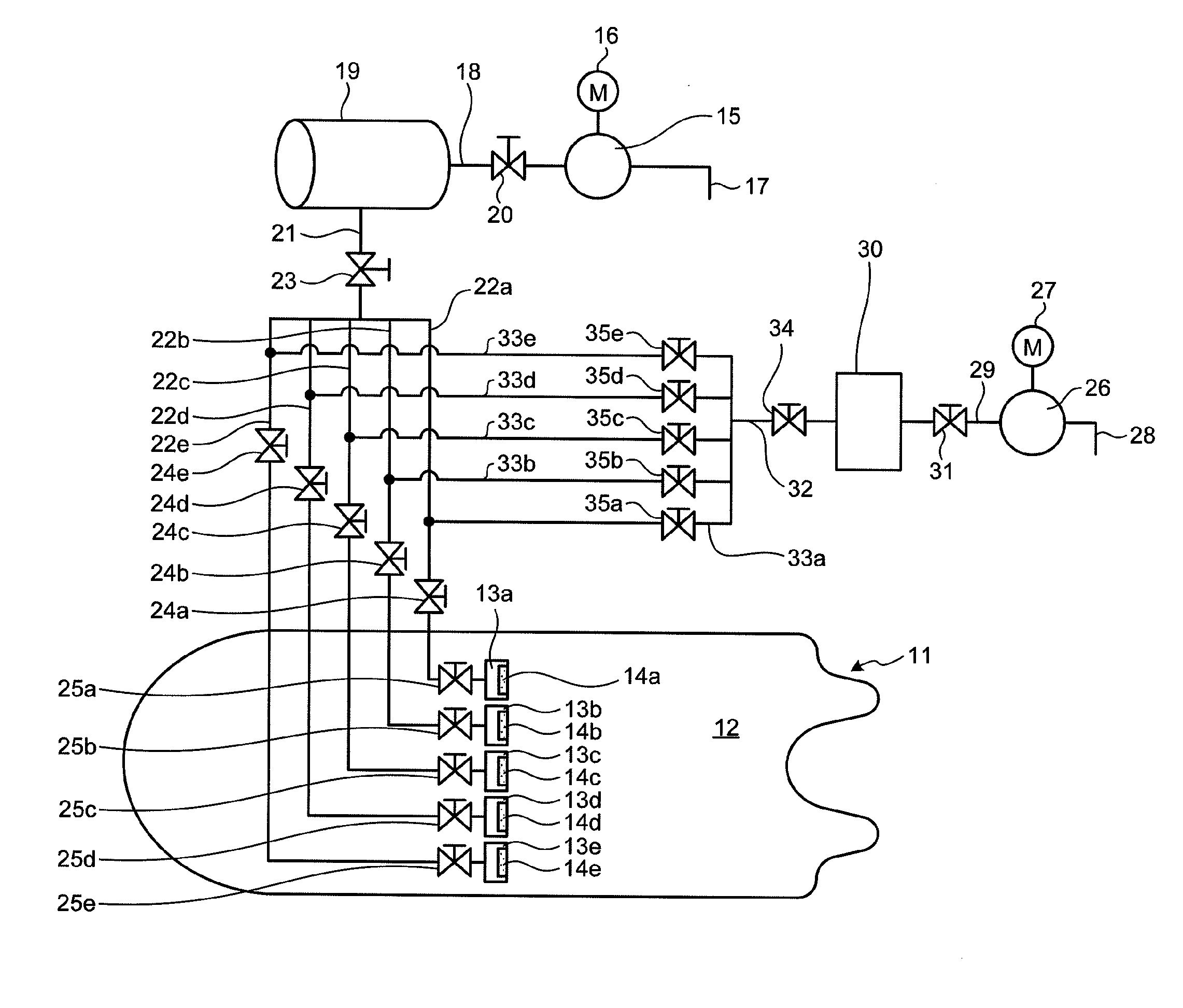
[0014]According to an embodiment of the ship-body frictional resistance reducing device of the present invention, an air ejection hole provided on a bottom surface of a ship body, an air supply unit that supplies air to the air ejection hole, a marine-biofouling preventing-fluid supply unit that supplies a marine-biofouling preventing fluid to the air ejection hole, and a switching unit that connects either one of the air supply unit and the marine-biofouling preventing-fluid supply unit to the air ejection hole in a selective manner are provided. Therefore, when the air supply unit is connected to the air ejection hole by the switching unit, the air is ejected from the air ejection hole to the bottom surface of the ship body, by which frictional resistance of water exerted on an outer surface of the ship body can be reduced. On the other hand, when the marine-biofouling preventing-fluid supply unit is connected to the air ejection hole by the switching unit, the marine-biofouling preventing fluid is ejected from the air ejection hole, by which adhesion of marine species to the air ejection hole of the ship body can be prevented. At this time, because the air supply unit can be stopped, it is possible to suppress power consumption.
[0015]Furthermore, according to the ship-body frictional resistance reducing device of the present invention, the air supply unit includes an air supply source and an air supply path that connects the air supply source to the air ejection hole, the marine-biofouling preventing-fluid supply unit includes a marine-biofouling preventing-fluid supply source and a marine-biofouling preventing-fluid supply path that connects the marine-biofouling preventing-fluid supply source to the air supply path, and the switching unit includes a first on-off valve provided on a side closer to the air supply source than a connection portion with the marine-biofouling preventing-fluid supply path of the air supply path and a second on-off valve provided on the marine-biofouling preventing-fluid supply path. Therefore, it is possible to switch between the air and the marine-biofouling preventing fluid in an easy manner simply by operating each of the on-off valves.
[0016]Moreover, according to the ship-body frictional resistance reducing device of the present invention, a plurality of ejection chambers are provided on a bottom of the ship body in a width direction of the ship body, and a plurality of the air ejection holes are provided on each of the ejection chambers, the air supply path includes a primary air supply path extending from the air supply source and a plurality of secondary air supply paths branched from the primary air supply path and respectively connected to the ejection chambers, and the marine-biofouling preventing-fluid supply path includes a primary marine-biofouling preventing-fluid supply path extending from the marine-biofouling preventing-fluid supply source and a plurality of secondary marine-biofouling preventing-fluid supply paths branched from the primary marine-biofouling preventing-fluid supply path and respectively connected to the secondary air supply paths. Therefore, by connecting the marine-biofouling preventing-fluid supply source to the secondary air supply paths through the marine-biofouling preventing-fluid supply path, it is possible to supply the marine-biofouling preventing fluid to the air ejection holes of the ejection chambers in a proper manner, and as a result, it is possible to prevent the adhesion of the marine species to the air ejection holes in a proper manner.
[0017]Furthermore, according to the ship-body frictional resistance reducing device of the present invention, a plurality of ejection chambers are provided on a bottom of the ship body in a width direction of the ship body, and a plurality of the air ejection holes are provided on each of the ejection chambers, the air supply path includes a primary air supply path extending from the air supply source and a plurality of secondary air supply paths branched from the primary air supply path and respectively connected to the ejection chambers, and the marine-biofouling preventing-fluid supply path is connected to the primary air supply path. Therefore, by connecting the marine-biofouling preventing-fluid supply source to the primary air supply path through the marine-biofouling preventing-fluid supply path, it is possible to simplify a piping configuration and to achieve downsizing of facilities and low cost.
[0018]Moreover, according to the ship-body frictional resistance reducing device of the present invention, the switching unit connects the marine-biofouling preventing-fluid supply unit to the air ejection hole when a sailing speed of a ship is slower than a predetermined low speed that is set in advance. Therefore, by supplying the marine-biofouling preventing fluid to the air ejection holes at a speed lower than the predetermined low speed at which it is not possible to sufficiently reduce the frictional resistance by forming an air bubble curtain on the outer surface of the ship body, it is possible to suppress the power consumption in an optimum manner while achieving a reduction of the frictional resistance of the water exerted on the outer surface of the ship body and a prevention of the adhesion of the marine species to the air ejection holes at the same time.

Problems solved by technology

Therefore, there can be a case that sea water intrudes into the air chamber through a large number of the air ejection holes, and marine species such as shellfishes or seaweeds adhere to the air ejection holes and the like, and may block the air ejection holes.

Method used


Image

  • Device for reducing frictional resistance of ship body
  • Device for reducing frictional resistance of ship body
  • Device for reducing frictional resistance of ship body

Examples


first embodiment

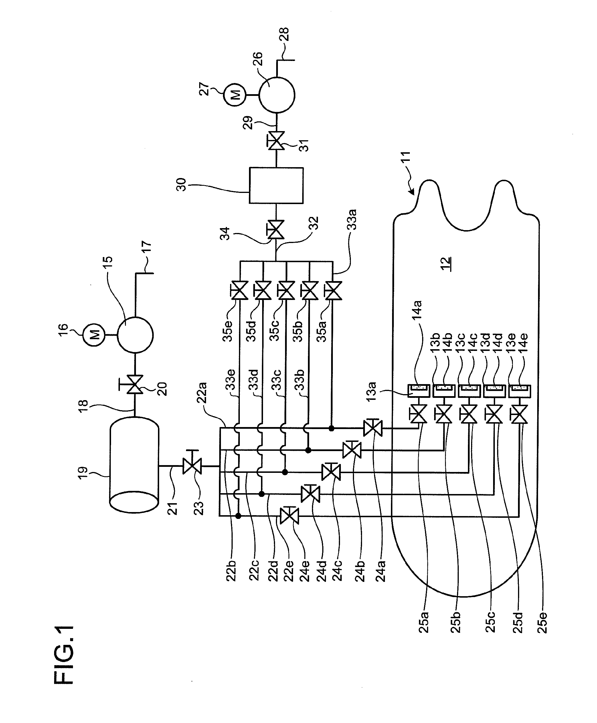
[0041]FIG. 1 is a schematic configuration diagram of a ship-body frictional resistance reducing device according to a first embodiment of the present invention.

[0042]In the ship-body frictional resistance reducing device according to the first embodiment, as shown in FIG. 1, a plurality of ejection chambers 13a, 13b, 13c, 13d, and 13e (five ejection chambers in the present embodiment) are arranged in a sequential arrangement on a bottom 12 of a ship body 11 of a ship along a width direction of the ship body 11. On lower surfaces of the ejection chambers 13a, 13b, 13c, 13d, and 13e, a plurality of air ejection holes 14a, 14b, 14c, 14d, and 14e are formed, respectively, along longitudinal directions of the ejection chambers 13a, 13b, 13c, 13d, and 13e, that is, the width direction of the ship body 11.

[0043]In practice, a slit-shaped opening is formed on the bottom 12 along the width direction of the ship body 11, the ejection chambers 13a, 13b, 13c, 13d, and 13e are fixed by welding o...

second embodiment

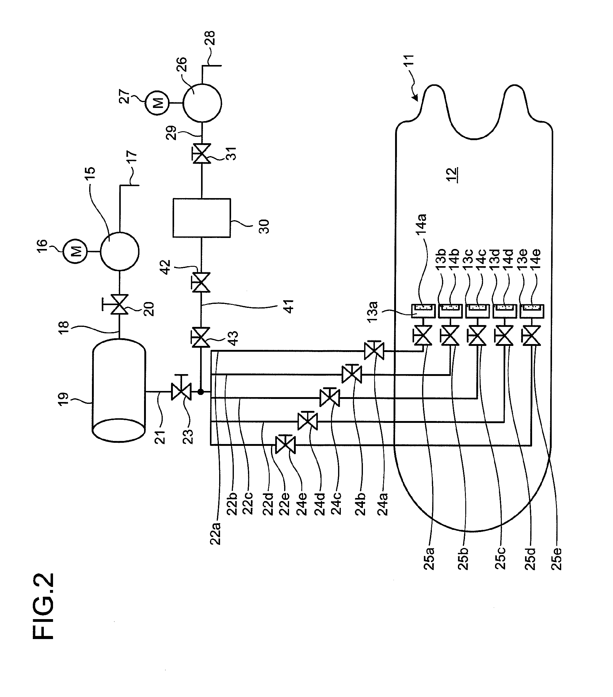
[0067]FIG. 2 is a schematic configuration diagram of a ship-body frictional resistance reducing device according to a second embodiment of the present invention. Members having functions identical to those explained in the above embodiment are denoted by like reference numerals and explanations thereof will be omitted.

[0068]In the ship-body frictional resistance reducing device according to the second embodiment, as shown in FIG. 2, a plurality of the ejection chambers 13a, 13b, 13c, 13d, and 13e are arranged in a sequential arrangement on the bottom 12 of the ship body 11 of a ship along a width direction of the ship body 11. On lower surfaces of the ejection chambers 13a, 13b, 13c, 13d, and 13e, a plurality of air ejection holes 14a, 14b, 14c, 14d, and 14e are formed, respectively, along the width direction of the ship body 11.

[0069]Meanwhile, the blower 15 is provided inside the ship body 11, which is connected to the main chamber 19 via the air supply pipe 18. The primary air su...


PUM


Abstract

In a ship-body frictional resistance reducing device, an ejection chamber (13a, 13b, 13c, 13d, and 13e) having an air ejection hole (14a, 14b, 14c, 14d, and 14e) is fixed to a bottom (12) of a ship body (11), an air supply path for supplying air to the ejection chamber (13a, 13b, 13c, 13d, and 13e) and a marine-biofouling preventing-fluid supply path for supplying a marine-biofouling preventing fluid to the ejection chamber (13a, 13b, 13c, 13d, and 13e) are connected to the ejection chamber (13a, 13b, 13c, 13d, and 13e), and an on-off valve (23, 34) is provided on each of the paths, by which either one of the paths can be connected in a selective manner, making it possible to prevent adhesion of marine species to the air ejection hole of the ship body while suppressing power consumption therefor.

Description

TECHNICAL FIELD[0001]The present invention relates to a ship-body frictional resistance reducing device for reducing frictional resistance of water exerted on an outer surface of a sailing ship body by covering the outer surface of the ship body with an air bubble curtain formed by ejecting air from a bottom of the ship body.BACKGROUND ART[0002]Generally, frictional resistance of water is exerted on a submerged outer surface of a bottom of a sailing ship, so that most of ship body resistance is the frictional resistance generated by a relative flow of the water on a ship's bottom. To handle this problem, there has been proposed a technique for reducing the frictional resistance of the ship body by covering an outer surface of the ship body with an air flow when the ship is sailing.[0003]This type of ship-body frictional resistance reducing device is configured by forming an opening portion on a ship's bottom, providing an air chamber in an opening portion, forming a large number of ...

Claims


Application Information

Patent Timeline
IPC IPC(8): B63B1/38B63B59/04A01M29/00A01M29/12A01M29/30
CPCB63B1/38Y02T70/122B63B59/04Y02T70/10
Inventor TAKANO, SHINICHIMIZOKAMI, SHUJIHIGASA, SEIJIROFURUYAMA, EIJIMATSUMOTO, HIROMITSU
Owner MITSUBISHI SHIPBUILDING CO LTD
Learn More