Overpressure Protection System and Method for a Hyperbaric Chamber

a protection system and hyperbaric chamber technology, applied in the direction of valve operation/release device, respirator, treatment room, etc., can solve the problems of increased risk of injury to those in the room or the patient in the chamber, affecting the function of the emergency ventilation mechanism, and compromising the safety of the system

Inactive Publication Date: 2011-05-12
WOOD JOHN STEVEN
View PDF18 Cites 3 Cited by
  • Summary
  • Abstract
  • Description
  • Claims
  • Application Information

AI Technical Summary

Benefits of technology

[0012]The present invention aims to address such concerns by, in the event of a fire, or other situation resulting in an overpressure condition in the chamber, simultaneously (or nearly simultaneously) actuating the chamber's emergency vent valve and terminating oxygen flow. The invention is a system connectable between a hyperbaric chamber and its corresponding oxygen supply that, upon over-pressurization of the chamber, shuts off the oxygen supply to the chamber and simultaneously activates the chamber's emergency ventilation system. Specifically, the present invention eliminates the need for the operator to close supply valves and actuate the emergency ventilation shut off.

Problems solved by technology

When dealing with a pure oxygen environment, there are several significant risks.
For example, pure oxygen supports combustion, and any spark or unintentional open flame could lead to an explosion.
Also, if the recommended pressure is exceeded within the hyperbaric chamber, the chamber might structurally fail, which can cause the chamber to blow apart at high speed with an additional risk of injury to those in the room or the patient in the chamber.
In some chamber designs, if the supply gas to the chamber is interrupted, function of the emergency ventilation mechanism may be compromised because the emergency ventilation system requires a gas supply to operate.
Although hyperbaric chambers as they exist today are relatively safe, there are instances where patients and others have been injured or killed as a result of the failures of the existing safety systems.
For example, in one incident, a fire initiated by an ignition source introduced by the patient caused fatal burns to the patient.
The chamber exploded, and parts of the chamber impacted the patient's wife at a high rate of speed, resulting in her death.

Method used


Image

  • Overpressure Protection System and Method for a Hyperbaric Chamber
  • Overpressure Protection System and Method for a Hyperbaric Chamber

Examples


Embodiment Construction

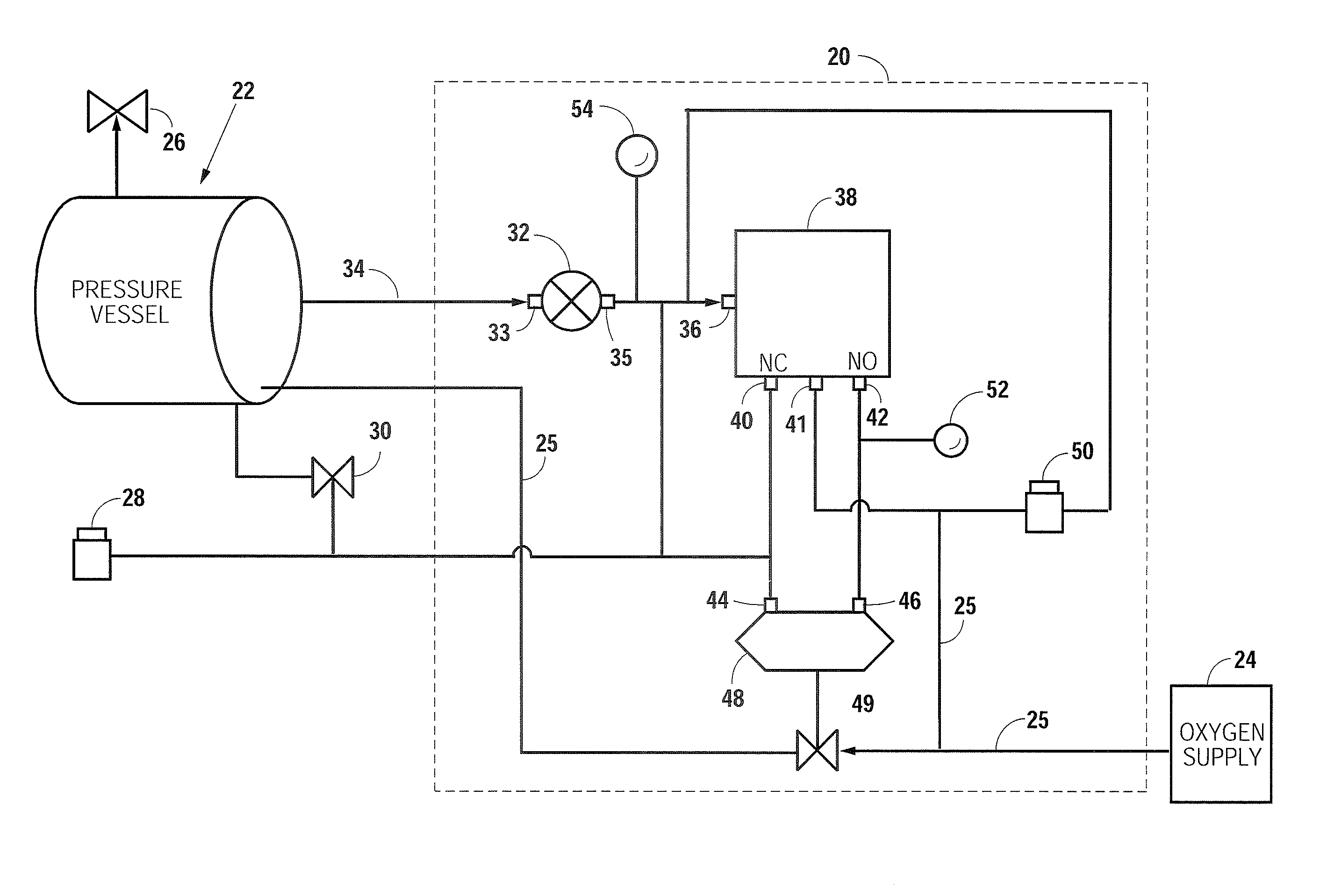
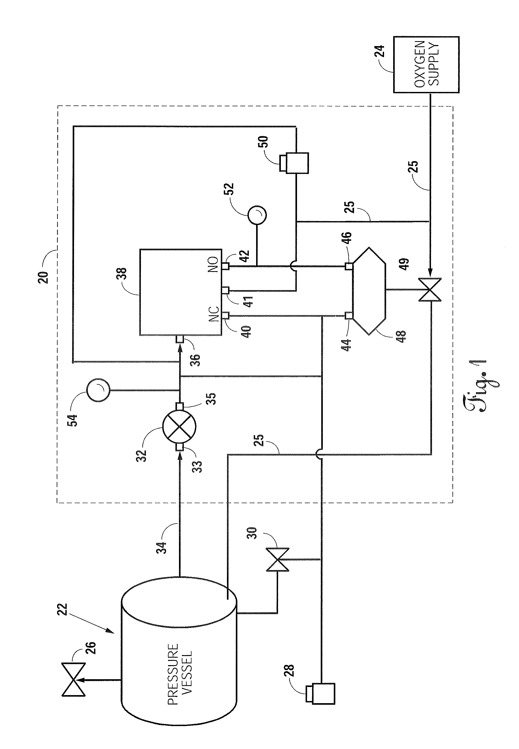
[0017]FIG. 1 is a system diagram of a preferred embodiment of an overpressure protection system 20 having the features of the present invention and interposed between a hyperbaric chamber 22 and an oxygen supply 24. The chamber 22 receives oxygen from a supply line 25 connected to the oxygen supply 24, and is set to operate at a maximum chamber set point to result in a predetermined absolute pressure, which is typically three atmospheres absolute.

[0018]During normal operation, the chamber 22 receives oxygen from the oxygen supply 24 through the supply line 25. The chamber 22 include a chamber relief valve 26 typically configured to open at a predetermined relief valve pressure to prevent overpressurization. Alternatively, in the event an operator detects an overpressure condition or otherwise needs to quickly remove a patient from the chamber 22, depressing an emergency actuation button 28 actuates emergency vent valve 30 to cause the pressure within the chamber 22 to vent. In addit...


PUM


Abstract

An overpressure protection system and method for a hyperbaric chamber having a secondary relief valve in pressure communication with a hyperbaric chamber and configured to actuate upon occurrence of a predetermined pressure condition. Actuation of the secondary relief valve causes an output signal to be delivered to a relay input, which results in actuation of an emergency vent valve to close an oxygen shutoff valve to terminate the flow of oxygen to the chamber. In the preferred embodiment, the predetermined pressure condition occurs when the chamber pressure exceeds the maximum chamber set point plus a predetermined pressure differential. In the preferred embodiment, the relay may be pneumatic or electromechanical.

Description

CROSS-REFERENCES TO RELATED APPLICATIONS[0001]Not applicable.STATEMENT REGARDING FEDERALLY SPONSORED RESEARCH OR DEVELOPMENT[0002]Not applicable.BACKGROUND OF THE INVENTION[0003]1. Field of the Invention[0004]The present invention relates to a safety system and method for use with hyperbaric chambers. More specifically, the invention is an overpressure protection system and method for interposition between a hyperbaric chamber and a corresponding oxygen supply that both vents the chamber and shuts off oxygen flow upon the occurrence of a predetermined pressure condition. An improved hyperbaric chamber incorporating an overpressure protection system is also provided.[0005]2. Description of the Related Art[0006]Hyperbaric chambers are used in diving to help alleviate symptoms of decompression sickness as well as in the treatment of wounds and disease. During use, the patient sits or lays inside the hyperbaric chamber, typically on a mattress in the supine position, whereafter the hype...

Claims


Application Information

Patent Timeline
Patent Type & Authority Applications(United States)
IPC IPC(8): A61M16/20
CPCA61G10/026Y10T137/7762Y10T137/7769
Inventor WOOD, JOHN STEVEN
Owner WOOD JOHN STEVEN
Why Eureka
Try Eureka