Counter rotation subsurface current generator

a subsurface current and generator technology, applied in the direction of electric generator control, machines/engines, liquid fuel engines, etc., can solve the problems of significant kinetic power loss, reduce service cost, increase the drag on the apparatus, and increase the reliability of the generator

Active Publication Date: 2011-05-12
GREYSHOCK PAUL
View PDF6 Cites 16 Cited by
  • Summary
  • Abstract
  • Description
  • Claims
  • Application Information

AI Technical Summary

Benefits of technology

[0022]It is another object of the invention to eliminate several categories of maintenance problems, thus reducing service cost and increasing the reliability of the generator. As a positive buoyant apparatus controlled by internal micro pressure switches that regulate raising and submerging allows the apparatus to be towed to current farm sites, ballast and submerged to optimum depth where current is strongest in flow and density. As current increases there is increased drag on the apparatus to push it deeper, by monitoring and controlling outside pressure keeps apparatus at ideal depth for optimum power production. The apparatus is a propulsion system controlling compressed high and low pressure volumes through internal regulation ports, and internal monitoring or speed and depth pressure to produce maximum conversion of hydro kinetic energy into mechanical energy for production of electricity.

Problems solved by technology

To work at such depths is difficult to seal and prevent high pressure water from entering the gearbox and generator, resulting in significant kinetic power loss with foreseeable maintenance issues caused from high external pressure of outside water.

Method used


Image

  • Counter rotation subsurface current generator
  • Counter rotation subsurface current generator
  • Counter rotation subsurface current generator

Examples


Embodiment Construction

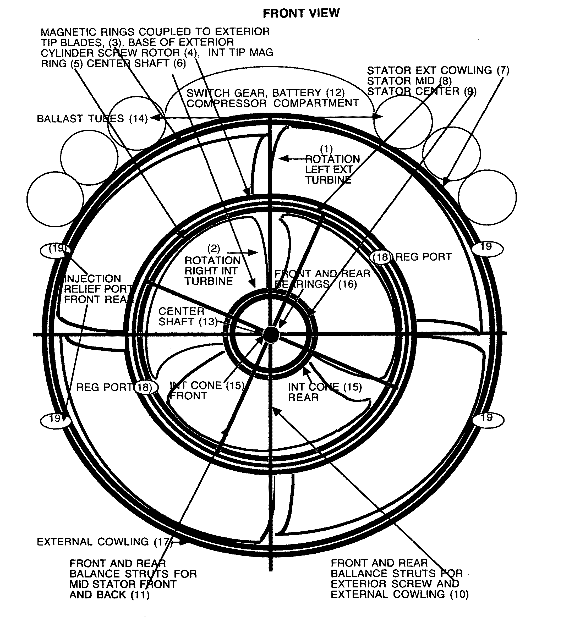
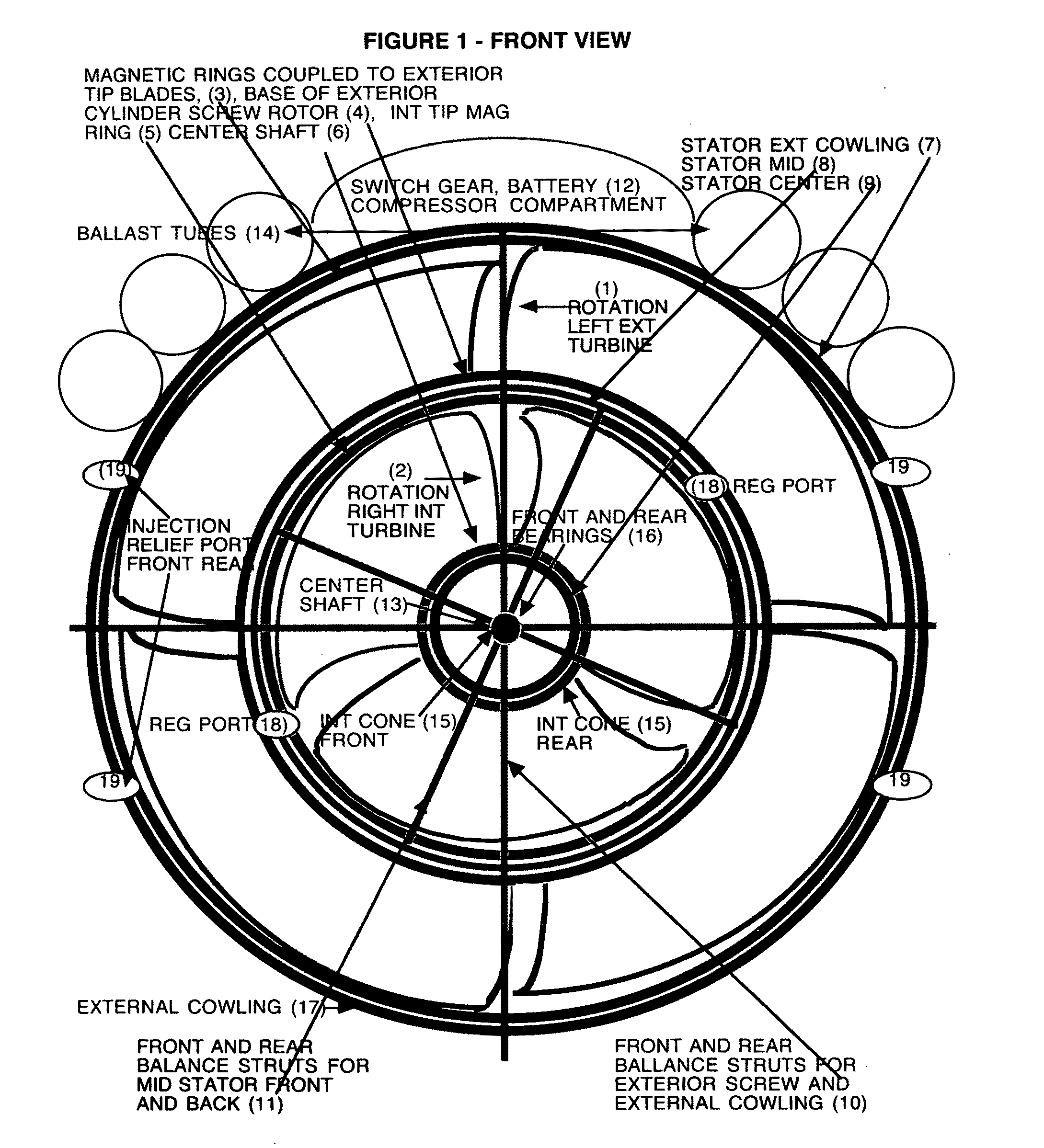
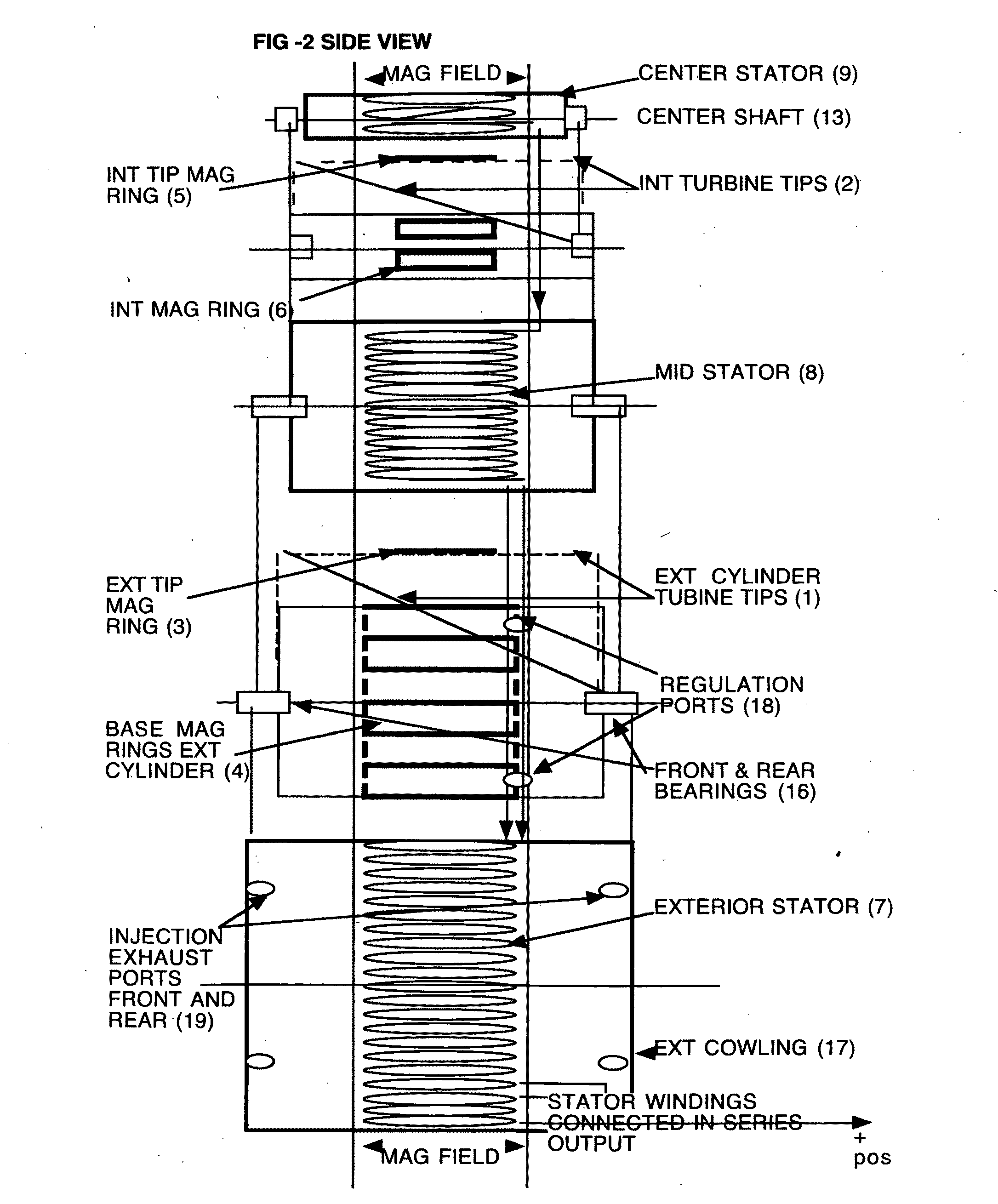
[0025]The present invention is a method and apparatus for capturing and converting the kinetic energy from flowing currents and producing mechanical energy for production electricity, the invention is, but not limited to a 1:2 (diameter to length ratio) having two counter rotation turbine's (1) and (2) rotating within cowling (17) that maximizes current through turbines, wherein, the interior turbine compresses ocean current into a higher pressure that is released into the low pressure area of exterior turbine (1) generating additional draft and mechanical power to increase electrical energy output.

FIG. 1

Front End View

[0026]EXTERIOR TURBINE (1) from the FRONT extends longitudinally to the REAR with blade pitch 120 degrees to the RIGHT (CLOCKWISE ROTATION). INTERIOR TURBINE (2) from the FRONT extends longitudinally to the REAR with turbine blade pitch 120 degrees to the LEFT (COUNTER CLOCKWISE ROTATION). CENTER CONE (15) from the FRONT tapers to the larger diameter at the REAR. EXTER...


PUM


Abstract

An invention for capturing and converting the hydro kinetic energy in ocean and tidal currents into mechanical energy for generating electricity. An internal turbine enclosed in a external turbine cylinder rotates opposite of internal turbine. Current is compressed into high pressure within internal turbine, the high pressure is vented into the rear low pressure side of external turbine producing additional energy. The internal and external turbines are enclosed in a cowling to maximize current through both counter rotating turbines. Permanent magnet rings are coupled to both turbine tips that rotate peripheral to stators. The cowling and turbines are balanced around the main center shaft, it is finned at the rear to steer the apparatus into the current. Counter rotation produces a neutral output torque with increased energy output that is transmitted via underwater cable to onshore grid.

Description

BACKGROUND OF THE INVENTION[0001]The present invention relates to the generation of mechanical power from the renewable power in ocean, tidal and wind currents. It's concept can produce renewable energy in favorable regions where ocean thermal currents flow close to land regions (i.e. the Florida Straits) that would benefit from this untapped resource of energy.DESCRIPTION OF THE PRIOR ART[0002]There is an increasing need for greater amounts of electrical power, and an increasing concern to minimize pollution of the environment caused by generating electrical power from carbon emitting power stations. Consequently, inventions have been devised for harvesting power from tidal and ocean current. The estimated total worldwide power in ocean currents has been estimated to be about 5,000 GW, with power density up to 75 kW / m2, at deep depths.[0003]The present invention addresses the difficulty in extracting usable portions of this slow moving high-density power in an economical achievable...

Claims


Application Information

Patent Timeline
Patent Type & Authority Applications(United States)
IPC IPC(8): F03B13/00F04D29/42
CPCF03B13/00Y02E10/725F03B13/26Y02E10/72
Inventor GREYSHOCK, PAUL A.
Owner GREYSHOCK PAUL
Why Eureka
Try Eureka