Arrangement for cooling of an electrical generator

a technology for electrical generators and cooling arrangements, applied in the direction of electric generator control, magnetic circuit shape/form/construction, magnetic circuit rotating parts, etc., can solve the problems of generating significant heat, eddy current loss, induced current, etc., and achieve the effect of improving the cooling arrangemen

Inactive Publication Date: 2011-05-12
SIEMENS AG
View PDF15 Cites 41 Cited by
  • Summary
  • Abstract
  • Description
  • Claims
  • Application Information

AI Technical Summary

Benefits of technology

[0026]It is therefore the aim of the present invention, to provide an improved cooling arrangement for an electrical generator, especially for a large electrical generator like a direct drive generator in a wind turbine.

Problems solved by technology

This leads to induced currents, which generate significant heat in the stator-cores and stator-coils.
This results in a eddy current loss.
The eddy current loss may reach a significant level, especially for a large electrical machine like a direct drive generator in a wind turbine.
Due to the heat the isolation of the metallic winding MW may be damaged, thus the temperature of the winding needs to be cooled down to achieve a predetermined lifetime of the electrical machine.
The drawback of this method is that large gas-to-air or gas-to-water heat exchangers are needed.
The drawback of this method is that a considerable temperature gradient will exist between the stator winding and the cooling medium due to the moderate heat conductivity of the laminate iron.
Thus it is difficult to maintain the temperature of the winding below a required maximum value.
The drawback of this method is that numerous joints are needed—for the electrical connection and for the connection of the hollow copper bars.
Therefore this method is only used in very large generators.
Another drawback is that the cooling pipes are exposed to the same electromagnetic fields as the coil-windings, thus voltages will be induced in the cooling pipes, which are made of metal.
The drawback of this method is that the deformation of the cooling tubes may lead to small cracks in the tubes.
These cracks may enlarge over time, for example due to corrosion, environmental influences or material characteristics.
Thus the cracks will result in leaks later.
Another drawback of this method is that the length of the cooling tubes increases if the method is used in large electrical machines.
Thus the section of the stator, which contains the main part of the serpentine, will not be cooled sufficiently.

Method used


Image

  • Arrangement for cooling of an electrical generator
  • Arrangement for cooling of an electrical generator
  • Arrangement for cooling of an electrical generator

Examples


Embodiment Construction

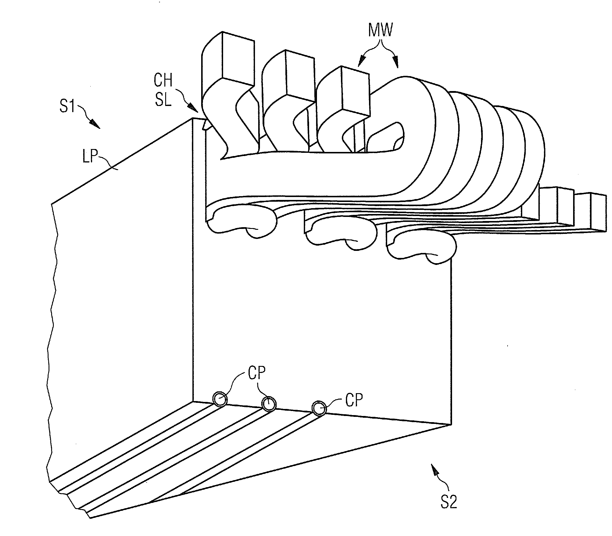
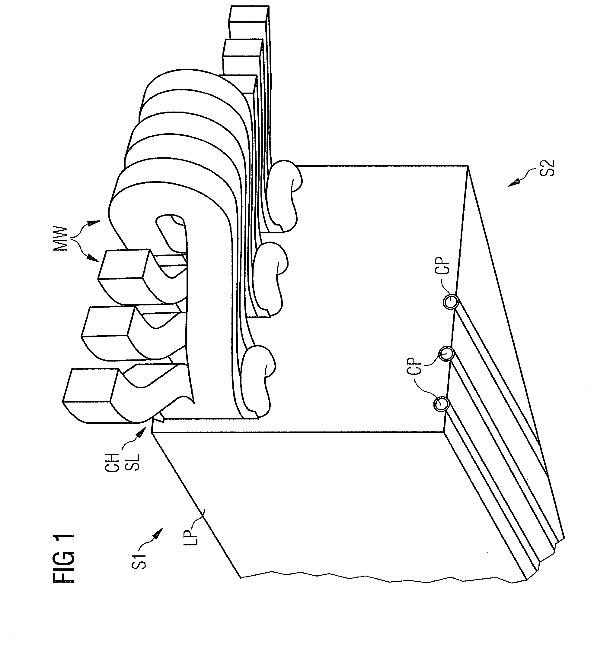
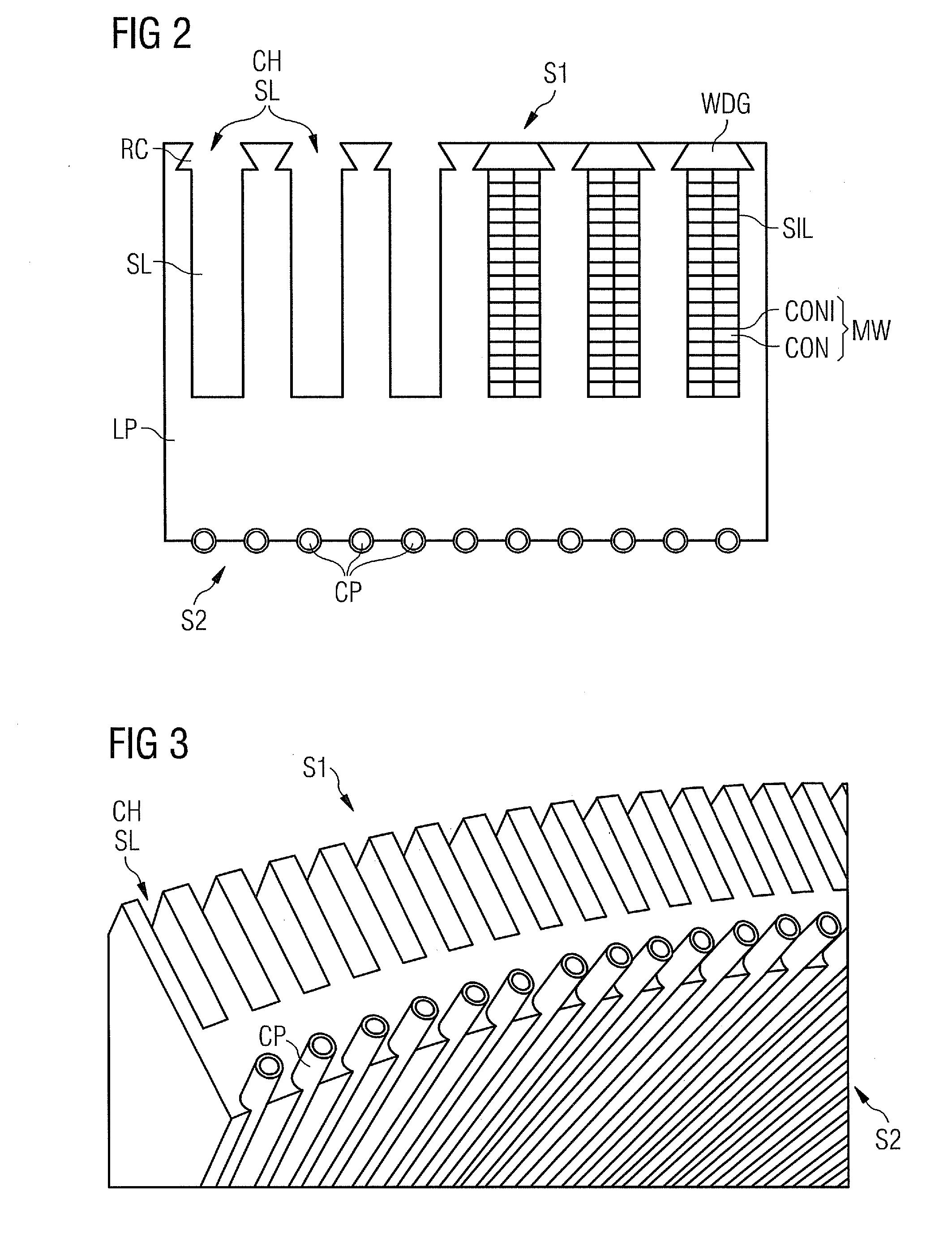
[0063]FIG. 1 shows a part of the cooling-arrangement invented,

[0064]A number of laminate plates LP are stacked. Each laminate plate LP shows a number of slots SL. Because of the stacking the slots SL form a number of channels CH, which are used to support metal-windings MW of a stator-coil.

[0065]The stacked laminate plates LP are part of stator-segment. The stacked laminate plates LP show a first side S1, which is aligned to the rotor of the generator. The slots SL are located on this first side S1.

[0066]At least one cooling-pipe CP is partly integrated into the stacked laminate plates LP. The partly integrated cooling-pipes CP penetrate the laminate plates LP on a second side S2 of the stacked laminate plates LP. The second side S2 is opposite to the first side S1.

[0067]A heat transfer compound (not shown here) is arranged between the cooling-pipe CP and the stacked laminate plates LP. Thus the thermal conductivity of the thermal interface between irregular surfaces of the stacked ...


PUM


Abstract

The arrangement directed to a generator, which contains a rotor and a stator us disclosed. The stator contains at least two stator segments. At least one of the stator segments contains a number of stacked laminate plates. The stacked laminate plates contain a number of slots at a first side, while the first side of the stacked laminate plates is aligned to the rotor. The slots support a metal-winding of a stator coil. At least one hollow cooling-pipe is partly integrated into the stacked laminate plates of the stator segment to cool its laminate plates by a cooling-medium, which is located into the cooling-pipes.

Description

CROSS REFERENCE TO RELATED APPLICATIONS[0001]This application claims priority of European Patent Office application No. 09013958.5 EP filed Nov. 6, 2009, which is incorporated by reference herein in its entirety.FIELD OF INVENTION[0002]The invention relates to an arrangement for cooling of an electrical generator, to be used in a wind-turbine preferably.BACKGROUND OF INVENTION[0003]During the operation of a generator in a wind turbine magnetic fields are induced from a rotor. The rotor contains permanent magnets or wound poles, which induce the magnetic fields into stator-cores and stator-coils. This leads to induced currents, which generate significant heat in the stator-cores and stator-coils.[0004]Additional eddy currents contribute to the generation of heat. Eddy currents are generated when a conductor is exposed to a changing magnetic field due to a relative motion of the conductor and the magnetic field force. Eddy currents are also generated due to variations of the magnetic ...

Claims


Application Information

Patent Timeline
Patent Type & Authority Applications(United States)
IPC IPC(8): F03D9/00H02K9/19F28F1/00H02K1/20H02K5/18
CPCF03D9/002F05B2260/201H02K1/20H02K7/1838Y02E10/722Y02E10/725Y02T50/675H02K1/16H02K2213/12H02K9/19F03D9/25F03D80/60Y02E10/72Y02T50/60H02K9/197
Inventor STIESDAL, HENRIK
Owner SIEMENS AG
Why Eureka
Try Eureka