
Vehicle seat for cooling and heating

a technology for vehicles and seats, applied in the direction of chairs, transportation and packaging, vehicle arrangements, etc., can solve the problems of poor ventilation of vehicles with such a structure, driver's loss of concentration while driving, and driver's discomfort, so as to simplify the ventilation structure, maximize the blowing performance, and improve the comfort of seating

Active Publication Date: 2011-05-12
HYUNDAI TRANSYS INC
View PDF21 Cites 90 Cited by
  • Summary
  • Abstract
  • Description
  • Claims
  • Application Information

AI Technical Summary

Benefits of technology

[0010]Various aspects of the present invention provide a vehicle seat for cooling and heating, in which air passages are maintained stable in order to maximize blowing performance, seating comfort is improved so that a user does not sense a foreign body when seated on the vehicle seat, and a ventilation structure can be simplified to reduce manufacturing costs while improving productivity.
[0011]Also provided is a vehicle seat for cooling and heating, in which blowing performance and blowing positions can be changed at low cost.
[0019]According to exemplary embodiments of the present invention as set forth above, the vehicle seat for cooling and heating has the following effects:
[0020]First, air passages are maintained stable to maximize blowing performance, seating comfort is improved so that the user does not sense a foreign body when seated on the vehicle seat, and the simplified ventilation structure can reduce manufacturing costs while improving productivity.
[0021]In addition, the blowing performance and blowing positions of the vehicle seat for cooling and heating can be changed at low cost.

Problems solved by technology

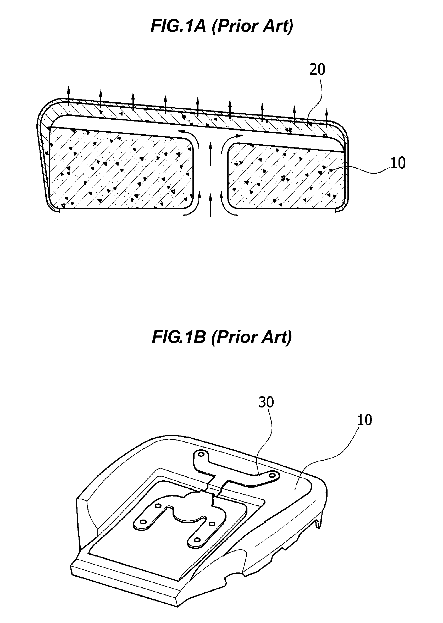
However, the vehicle seat having such a structure does not provide good ventilation.
In summer, a driver may feel uncomfortable due to sweat moistening the buttocks, which are in contact with the seat.
This may act as a factor that causes the driver to lose concentration while driving.
In addition, this structure is too expensive because the mold of the seat pad 10 has to be changed in order to improve its performance.

Method used


Image

  • Vehicle seat for cooling and heating
  • Vehicle seat for cooling and heating
  • Vehicle seat for cooling and heating

Examples


Embodiment Construction

[0034]Reference will now be made in detail to various embodiments of the present invention(s), examples of which are illustrated in the accompanying drawings and described below. While the invention(s) will be described in conjunction with exemplary embodiments, it will be understood that present description is not intended to limit the invention(s) to those exemplary embodiments. On the contrary, the invention(s) is / are intended to cover not only the exemplary embodiments, but also various alternatives, modifications, equivalents and other embodiments, which may be included within the spirit and scope of the invention as defined by the appended claims.

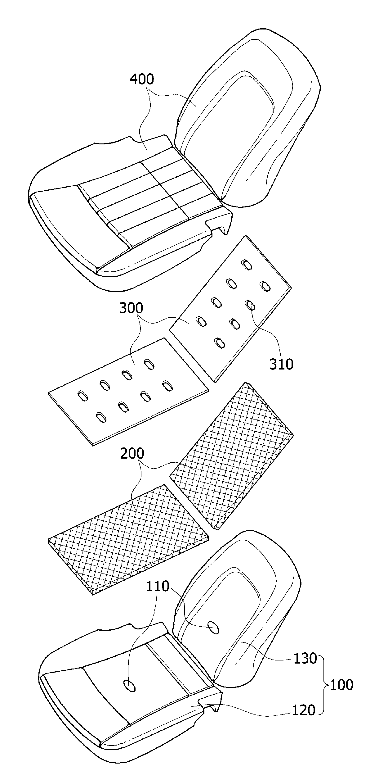
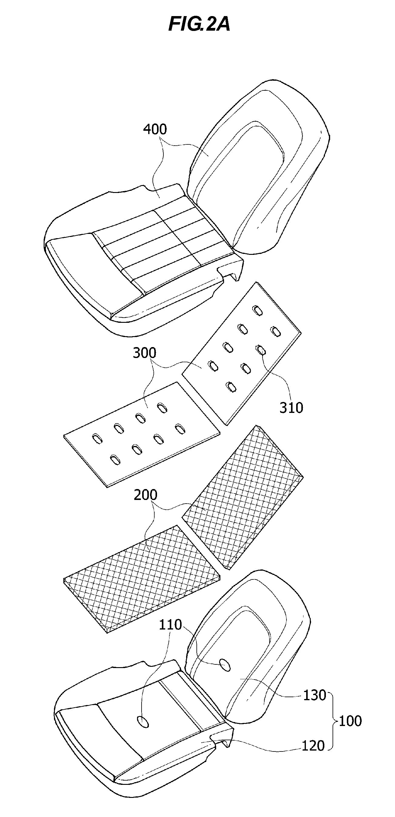
[0035]FIG. 2A is an exploded perspective view showing a vehicle seat according to one exemplary embodiment of the present invention, FIG. 2B is a cross-sectional view of the vehicle seat shown in FIG. 2A, showing the flow of air inside the seat, FIG. 3A is an exploded perspective view showing a vehicle seat according to another exempl...


PUM


Abstract

A vehicle seat for cooling and heating may include a seat pad, a mesh sheet having a certain thickness, a first film, and a porous seat cover, which are arranged sequentially in the direction in which air is introduced to flow. The seat pad has a pad hole, which allows air to pass through, and includes one or both of a seat cushion pad, which supports the buttocks of a user, and a seatback pad, which supports the upper body of the user. The mesh sheet has a porous network structure, through which air easily passes. The first film has a first film hole, which allows air to pass through. Air passages are maintained stable to maximize blowing performance, seating comfort is improved, and a ventilation structure is simplified to reduce manufacturing costs while improving productivity.

Description

CROSS REFERENCE TO RELATED APPLICATION[0001]The present application claims priority to Korean Patent Application Number 10-2009-0108408, filed on Nov. 11, 2009, the entire contents of which application are incorporated herein for all purposes by this reference.BACKGROUND OF THE INVENTION[0002]1. Field of the Invention[0003]The present invention relates to a vehicle seat for cooling and heating, and more particularly, to a vehicle seat for cooling and heating which includes a seat pad, a mesh sheet having a certain thickness, a first film, and a porous seat cover, which are arranged sequentially in the direction in which air is introduced to flow, the seat pad having a pad hole, which allows air to pass through, and including one or both of a seat cushion pad, which supports the buttocks of a user, and a seatback pad, which supports the upper body of the user, the mesh sheet having a porous network structure, through which air easily passes, and the first film having a first film hol...

Claims


Application Information

Patent Timeline
Patent Type & Authority Applications(United States)
IPC IPC(8): B60N2/56B60N2/90
CPCB60N2/5642B60N2/5685B60N2/5657B60N2/56B60H1/00
Inventor PARK, JANG SUPARK, CHAN UKOH, MAN JU
Owner HYUNDAI TRANSYS INC
Learn More