Blower and electric apparatus including the same

Active Publication Date: 2011-09-01
PANASONIC CORP
View PDF16 Cites 4 Cited by
  • Summary
  • Abstract
  • Description
  • Claims
  • Application Information

AI Technical Summary

Benefits of technology

[0016]With the above configurations, the inlet, the dust-proof performance of the fan, and the outlet satisfy the relationship A<C, A<B. Thus, the dimension

Problems solved by technology

Therefore, it is likely that the configuration of a conventional heat dissipation device cannot dissipate heat sufficiently.
Moreover, in the case of the electric apparatus for which compactness is critical such as the notebook PC, the arrangement of the blowing fan and the heat dissipation fin is limited strictly.
Although the cooling performance of the heat dissipation unit may be improved by making the inlet and the outlet larger, there is the problem of dust entering easily.
In particular, when the el

Method used


Image

  • Blower and electric apparatus including the same
  • Blower and electric apparatus including the same
  • Blower and electric apparatus including the same

Examples


embodiment 1

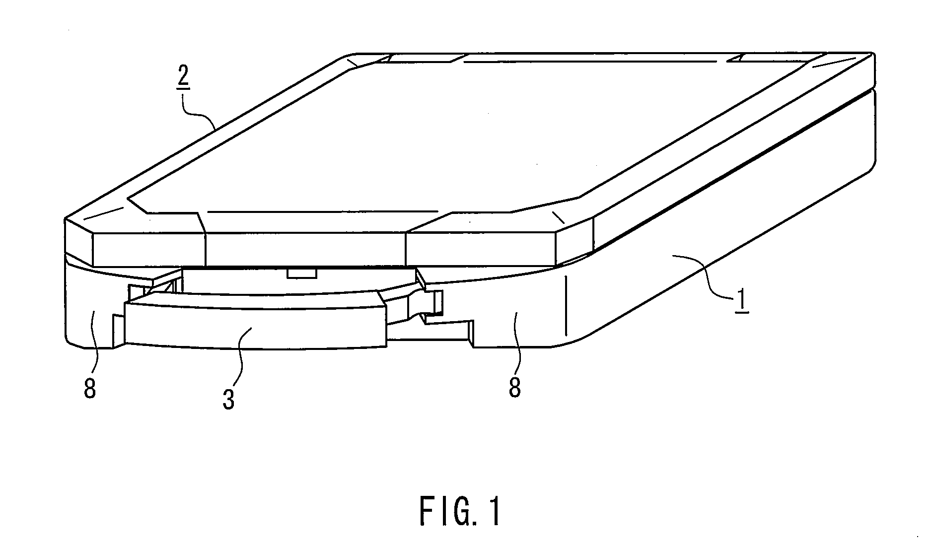
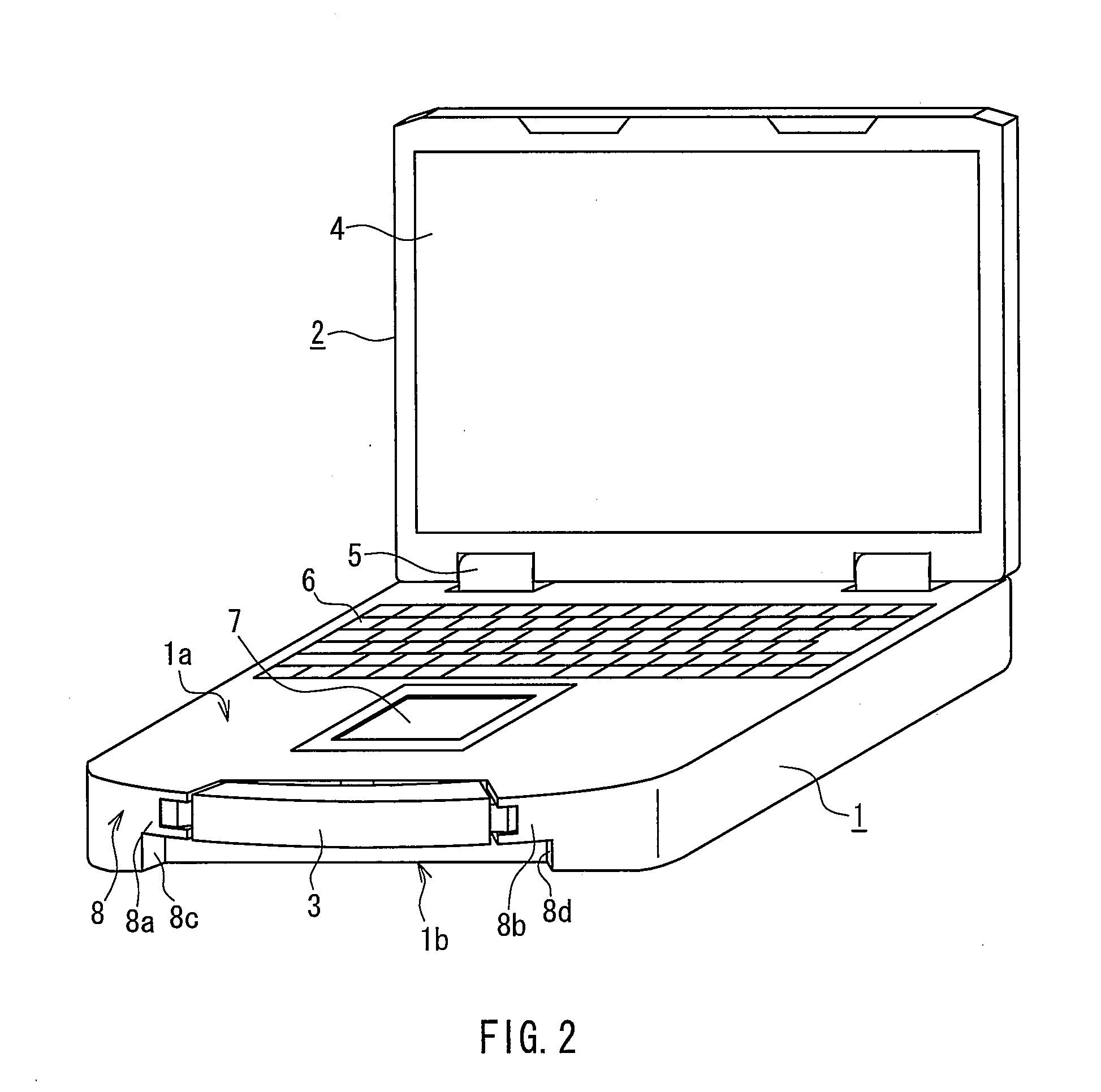
[0040]FIG. 1 is a perspective view showing the appearance of a notebook PC as an example of an electric apparatus in Embodiment 1. The notebook PC includes a main unit case 1, a display unit case 2, and a hand grip 3. FIG. 1 shows a non-operating state. FIG. 2 is a perspective view of the notebook PC in an operating state. The upper side and the lower side of the main unit case 1 when the notebook PC is in the operating state are defined as a main unit upper surface 1a and a main unit lower surface 1b, respectively.

[0041]The main unit case 1 contains a CPU, a circuit board on which various electric elements are mounted, a hard disk drive, a battery, or the like. The display unit case 2 is provided with a liquid crystal display 4 for displaying images, characters, or the like. The display unit case 2 is supported rotatably by the main unit case 1 with hinges 5. A keyboard 6 and a pointing device 7 are provided on the main unit upper surface 1a.

[0042]The pointing device 7 is fixed in...

embodiment 2

[0070]FIG. 11 is a cross-sectional view conceptually showing a heat dissipation unit of a warm-air blower as an example of an electric apparatus in Embodiment 2 of the present invention. In the basic configuration of this heat dissipation unit, the heat dissipation fin 13 of the heat dissipation unit of the notebook PC shown in FIG. 10 is replaced by a heater 18 (i.e., another heat-exchange element).

[0071]FIG. 12 is a cross-sectional view showing an example of a specific configuration of the warm-air blower including the heat dissipation unit. Since the basic configuration of this heat dissipation unit is the same as that of the heat dissipation unit shown in FIG. 7 in Embodiment 1, the same components are denoted by the same reference numerals, and a part of the explanation will not be repeated.

[0072]In this embodiment, the heat dissipation chamber 12 is formed inside a main unit case 19 of the warm-air blower and separated by the partition 11. The heat dissipation chamber 12 inclu...

embodiment 3

[0076]FIG. 13 is a cross-sectional view conceptually showing a dust collector composing, for example, a vacuum cleaner in Embodiment 3 of the present invention. In this configuration, there is a space between the fan region 16 and the inlet 15, and a dust collecting element 20 is located in the space. However, the dust collecting element 20 may be included in the inlet 15.

[0077]In this configuration, similarly to the above, the dimensions of each of the inlet 15 and the outlet 14 are determined to satisfy the relationship A15, B represents a particle size of dust that is allowed to pass through in view of the dust-proof performance of a fan in the fan region 16, and C represents a width of each of the slits or a diameter of each of the through holes of the outlet 14. Thus, the effect of improving both the blowing performance and the dust collection capability can be obtained within the range of dust-proof performance in which damage or functional degradation of the fan can be avoide...


PUM


Abstract

A blower includes a fan, an inlet through which air is drawn into the fan, and an outlet through which an air flow from the fan is exhausted. The inlet and the outlet have slits with a specific width or an array of through holes with a specific diameter. The relationship A<C, A<B is satisfied, where A represents the width of the slits or the diameter of the through holes of the inlet, B represents a particle size of dust that is allowed to pass through in view of the dust-proof performance of the fan, and C represents the width of the slits or the diameter of the through holes of the outlet. The blowing performance can be improved within the range of dust-proof performance in which damage or functional degradation can be avoided.

Description

BACKGROUND OF THE INVENTION[0001]1. Field of the Invention[0002]The present invention relates to a blower that includes a fan to draw air from an inlet and exhausts air through an outlet, and an electric apparatus that includes the blower.[0003]2. Description of Related Art[0004]For example, in the case of a notebook PC as an example of the electric apparatus, the amount of heat generated from a heat generating element such as a CPU increases as the performance of the notebook PC is improved. Therefore, it is likely that the configuration of a conventional heat dissipation device cannot dissipate heat sufficiently. Thus, a high-performance heat dissipation unit has been demanded. When the heat dissipation unit uses an air flow produced by a fan, the shape and arrangement of a heat dissipation fin, the interrelationship between the heat dissipation fin and a blowing fan (cooling fan), or the like have to be optimized.[0005]Moreover, in the case of the electric apparatus for which com...

Claims


Application Information

Patent Timeline
IPC IPC(8): H05K7/20F04D29/42
CPCF04D29/582F04D29/701G06F2200/1633G06F1/203G06F1/1656
Inventor SENOH, TOSHIYASATO, JUN
Owner PANASONIC CORP
Why Eureka
Try Eureka