Data processing apparatus and method for controlling the apparatus

a data processing apparatus and data processing technology, applied in the direction of digital output to print units, instruments, digital computers, etc., can solve the problems of inability to supply print data to the image processing circuit, the operation of the circuit and the processing speed of the fpga may be inferior to those of the asic,

Inactive Publication Date: 2011-05-12
CANON KK
View PDF7 Cites 20 Cited by
  • Summary
  • Abstract
  • Description
  • Claims
  • Application Information

AI Technical Summary

Benefits of technology

[0007]The feature of the present invention is to provide a data processing apparatus and method thereof in which a reconfiguration process of functions of a programmable logic of the data processing apparatus is executed by the programmable logic to reduce the load of a control unit of a CPU, etc. to improve the performance of data processing of the apparatus.

Problems solved by technology

However, in general, the circuit operation and the processing speed of the FPGA may be inferior to those of the ASIC.
Therefore, there is a problem that the print data cannot be supplied to the image processing circuit constituted by the FPGA during the reconfiguration of the functions of the FPGA.

Method used


Image

  • Data processing apparatus and method for controlling the apparatus
  • Data processing apparatus and method for controlling the apparatus
  • Data processing apparatus and method for controlling the apparatus

Examples


first embodiment

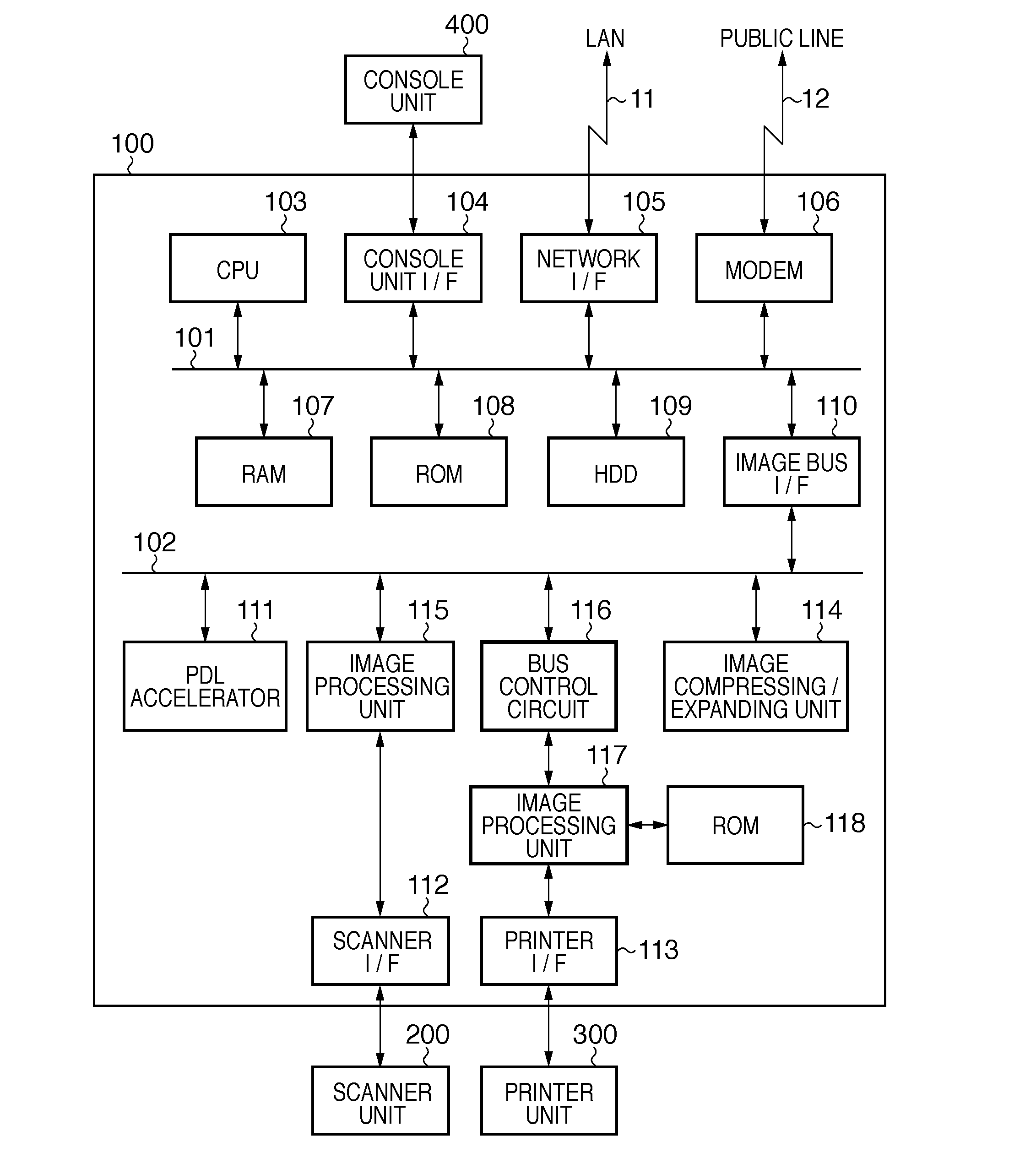
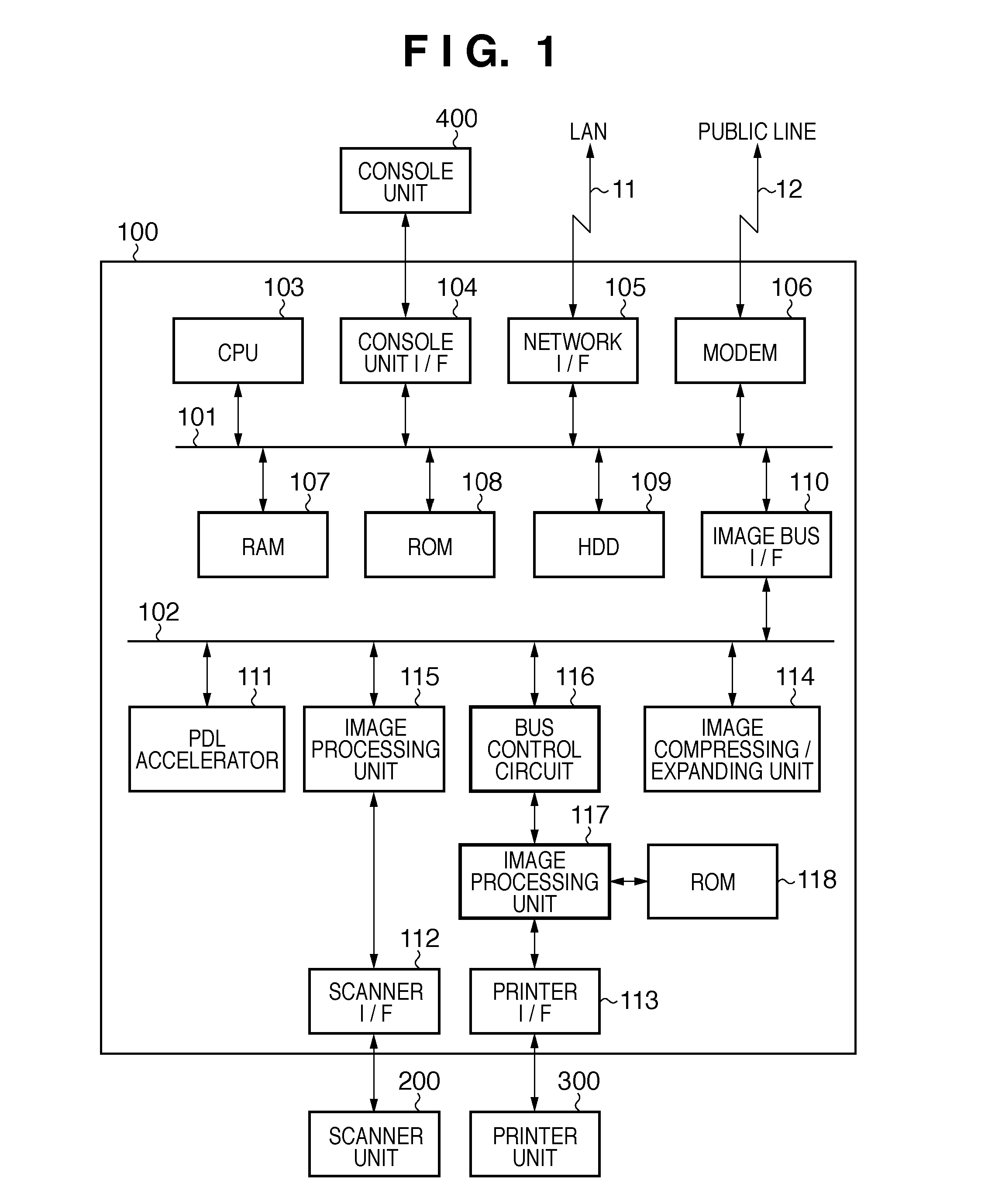
[0053]In the present invention, a processing method will be described, in which the image processing unit 117 of the multi function device (MFP) is constituted by the FPGA, and the multi function device receives a print job during processing of a copy job.

[0054]While the MFP executes the copy job, the image data scanned by the scanner unit 200 is inputted to the control unit 100 through the scanner I / F unit 112. The image processing unit 115 applies image processing, such as correction, processing, and edit, to the scanned image data. The image data is further compressed by the codec 114 if necessary and stored in the RAM 107 or the HDD 109 through the image bus 102, the image bus I / F 110, and the system bus 101.

[0055]The CPU 103 communicates with the printer unit 300, and when printing by the printer unit 300 is ready, the CPU 103 transmits the image data stored in the HDD 109 to the image processing unit 117 through the system bus 101, the image bus I / F 110, and the image bus 102....

second embodiment

[0078]As described at the beginning, specifications of size and operation speed of a circuit including the FPGA are not disclosed as those of the ASIC in some cases. In that case, the circuit is divided into two or more blocks. In a second embodiment, an internal module of the image processing unit 117 is divided into two, and two FPGAs are cascaded.

[0079]FIG. 13 is a block diagram showing a configuration, in which the data processing apparatus according to the second embodiment of the present invention is applied to the multi function device (MFP). The parts common to FIG. 1 are illustrated by the same reference numerals, and the description will not be repeated.

[0080]In FIG. 13, the image processing unit 117 of the control unit 100 of the MFP is divided into a first image processing unit 1300 and a second image processing unit 1301. In the second embodiment, the first image processing unit 1300 and the second image processing unit 1301 are connected in series via a second bus cont...


PUM


Abstract

The present invention provides a data processing apparatus having a programmable logic and a method for controlling the apparatus. If it is determined that the reconfiguration of the programmable logic is necessary, register setting data for reconfiguring the programmable logic is supplied to the programmable logic. The programmable logic reads out circuit information from a memory storing the circuit information in accordance with the register setting data and reconfigures a function of the programmable logic. A CPU transfers the register setting data to the programmable logic and then transfers data to be processed by the programmable logic whose function has been reconfigured, to the programmable logic.

Description

TECHNICAL FIELD[0001]The present invention relates to a data processing apparatus comprising a data processing circuit including a programmable logic and a method of controlling the data processing apparatus.BACKGROUND ART[0002]In recent years, a programmable logic, such as FPGA (Field Programmable Gate Array), constitutes a data processing circuit for specific application in many products. Previously, the FPGA has been often used as a tool for debugging in research and development. The use of the circuit that can be constituted by the FPGA has been expanded along with an improvement in the LSI manufacturing technology, and the manufacturing cost is reduced. Therefore, there is a trend of mounting the FPGA on various products. The cost can be particularly reduced in small-lot products compared to when ASIC (Application Specific Integrated Circuit) constitutes a data processing circuit for a specific application.[0003]However, in general, the circuit operation and the processing spee...

Claims


Application Information

Patent Timeline
Patent Type & Authority Applications(United States)
IPC IPC(8): G06F3/12
CPCH03K19/177H04N1/0097G06F3/1258G06F15/7867H04N2201/0094
Inventor NOMURA, YOSHIHISA
Owner CANON KK
Why Eureka
Try Eureka