Powerless external event detection device

a detection device and event technology, applied in the direction of instruments, building locks, static storage, etc., can solve the problems of device not being functional, device not being able to detect and record events, and device having a limited lifetim

Inactive Publication Date: 2011-05-12
EM MICROELECTRONIC-MARIN
View PDF4 Cites 17 Cited by
  • Summary
  • Abstract
  • Description
  • Claims
  • Application Information

AI Technical Summary

Problems solved by technology

Without such a power source or if the power source is OFF or if the energy stored in the battery becomes too low, this device will not be functional, i.e., it will be incapable of detecting and recording an event.
Furthermore, in the case of an internal power source like a battery, such a device will have a limited lifetime or the internal power source will have to be changed after a certain time period.
This causes a security problem first because there is a risk that the detection device becomes no longer functional when an interruption of the power supply occurs, and secondly because a perpetrator could cause an interruption of the power source, stopping the electrical supply of the detection device during the time period of the attempt.

Method used


Image

  • Powerless external event detection device
  • Powerless external event detection device
  • Powerless external event detection device

Examples


first embodiment

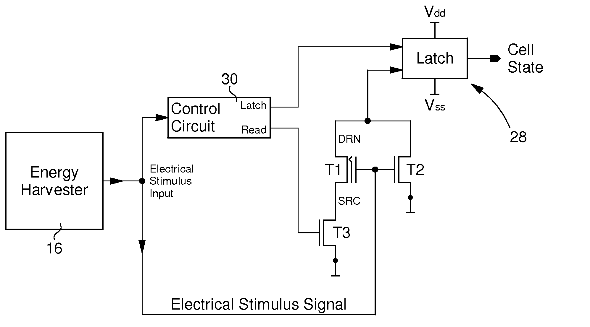
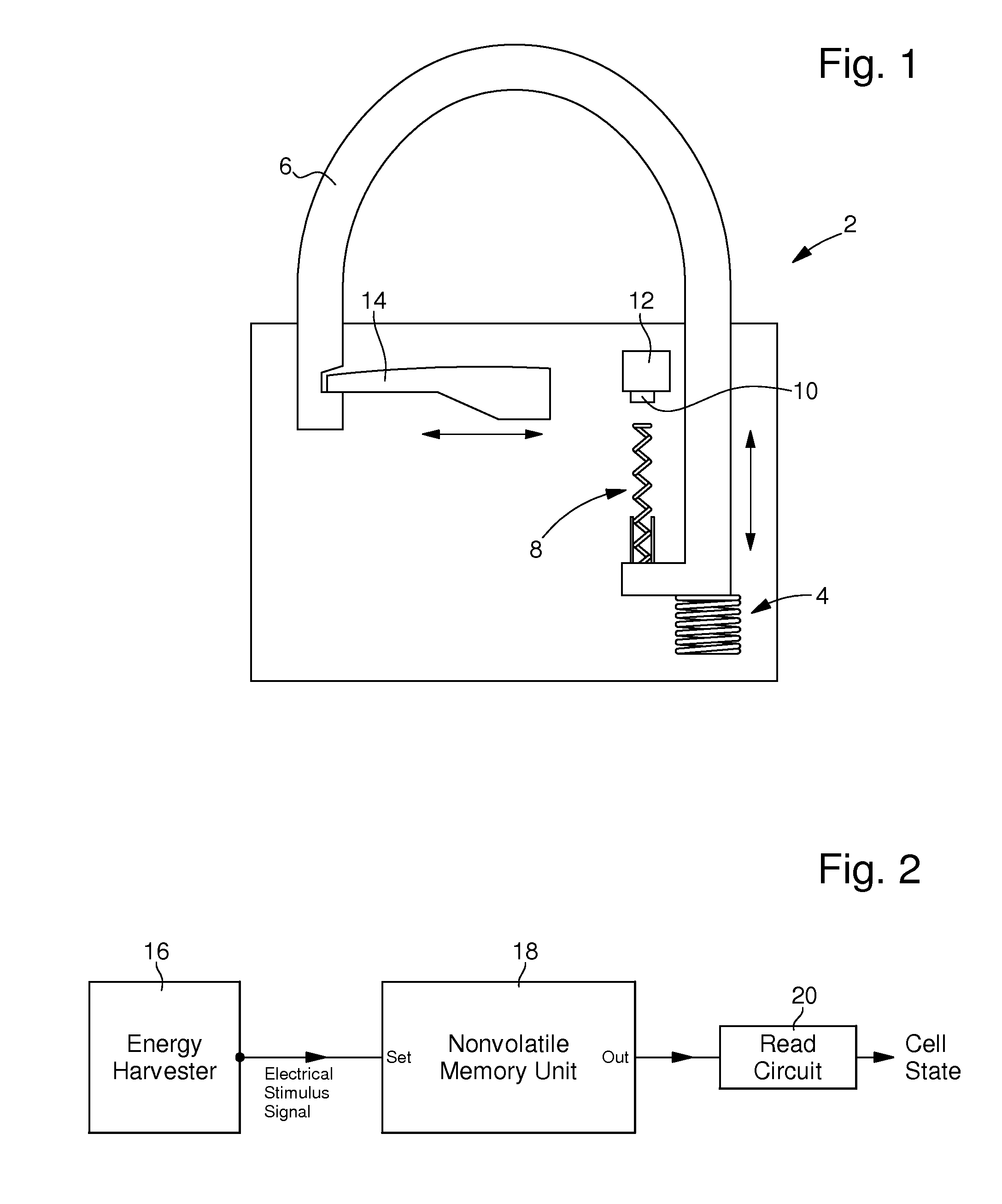
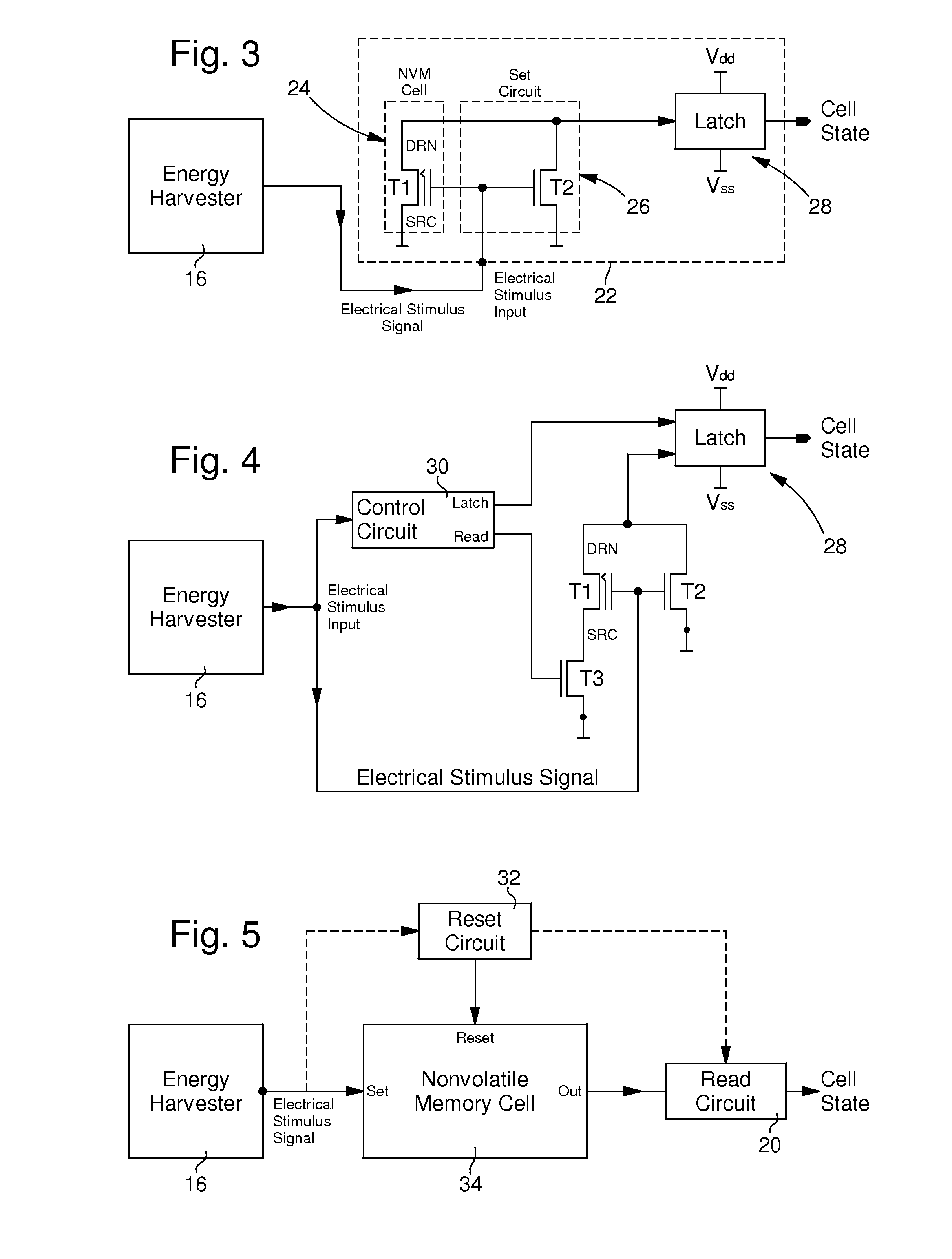
[0030]FIG. 2 shows the basic architecture of the external event detection device according to the invention. The DC electrical energy of an external event is collected by the sensor forming an energy harvester 16 and provided to a memory part of the electronic unit, in the variant of FIG. 2 formed by a Non-Volatile Memory (NVM) unit 18, comprising at least one NVM cell, through an electrical stimulus signal line. In the case of the lock of FIG. 1, this energy is provided by the force applied by the spring 8 on the piezoelectric element of the sensor 10. The memory part 18 is arranged for storing data relative to at least one external event detected by the external event sensor 16. According to the invention, the electronic unit is arranged for storing said data by using only the electrical energy contained in the electrical stimulus pulse generated by the external event acting on the sensor. Thus, the detection device of FIG. 2 defines a powerless detection device. This is also the ...

third embodiment

[0058]FIG. 6 shows a preferred electronic design of the The reset circuit is formed by a control circuit 40 and a level shifter 42 receiving a High Voltage (HV). The level shifter is controlled by the control circuit 40. In a variant, the level shifter can be formed by a high voltage inverter (CMOS Inverter). When the detection device is supplied, the latch 28 will automatically have a logical state corresponding to the logical state of the memory transistor T1. If this transistor T1 is set, the user takes note that a given external event has been detected. Then, the user can reset the memory cell so as to reuse the detection device. When a reset signal is received at the reset input of the control circuit 40, then the outputs of this control circuit are switched as follows:

[0059]The latch output is driven to 0 V instructing the latch to turn OFF for protecting itself from the high voltage which will be applied to the drain DRN of transistor T1.

[0060]The read output is driven to 0 ...


PUM


Abstract

The external event detection device comprises an electronic unit (22) and an external event sensor (16), the electronic unit having at least a non-volatile memory cell (24, T1) in which data relative to at least one external event detected by the external event sensor can be stored. According to the invention, the external event sensor defines an energy harvester that transforms energy from said at least one external event into electrical energy contained in an electrical stimulus pulse provided to the electronic unit. The electronic unit is arranged for storing said data by using only the electrical energy contained in the electrical stimulus pulse. In particular, the non-volatile memory cell is directly set to its written logical state from its initial logical state by the electrical stimulus pulse provided by said energy harvester. In a preferred embodiment, the electronic unit further comprises a set circuit (26) comprising a second FET transistor (T2) arranged between the ground of the electronic unit and the drain of a first FET transistor (T1) defining the non-volatile memory cell, this switch having a control gate connected to the control gate of the first FET transistor. The second FET transistor is turned on when an electrical stimulus pulse is provided to the electronic unit, connecting the drain (DRN) of the first FET transistor (T1) to ground and thus allowing the secure setting of the non-volatile memory cell.

Description

FIELD OF THE INVENTION[0001]The present invention concerns a powerless external event detection device. In particular, the present invention concerns a tamper event detection device for detecting a tamper event in a protected zone or in a closed case or container. By ‘powerless detection device’ it is understood that there is no internal or external power source supplying the device for allowing this device to detect an external event. However, such a powerless detection device can be supplied with power for other functions in defined time periods, e.g. for reading the state of a memory or for resetting such a device.[0002]The invention thus specifically deals with the reduction of the power consumption of such external event detection devices and furthermore with the increase in their security level.BACKGROUND OF THE INVENTION[0003]The detection of an attempt to recover secrets from / within a protected zone, closed case, or container through the use of an electronic circuit is often...

Claims


Application Information

Patent Timeline
Patent Type & Authority Applications(United States)
IPC IPC(8): G11C7/20
CPCE05B39/00
Inventor KAMP, DAVID A.MARINELLI, FILIPPOROZ, THIERRY
Owner EM MICROELECTRONIC-MARIN
Why Eureka
Try Eureka