Wind turbine generator system and operation control method therefor

a technology of operation control and wind power generator, which is applied in the direction of electric generator control, dynamo-electric converter control, instruments, etc., can solve the problem that the power at the interconnection node cannot be efficiently stabilized, and achieve the effect of improving the accuracy of reactive power adjustmen

Active Publication Date: 2011-05-12
MITSUBISHI HEAVY IND LTD
View PDF17 Cites 22 Cited by
  • Summary
  • Abstract
  • Description
  • Claims
  • Application Information

AI Technical Summary

Benefits of technology

[0023]The present invention provides the advantage of

Problems solved by technology

The conventional technique described above, however, has a problem in that the power at the interconnection node ca

Method used


Image

  • Wind turbine generator system and operation control method therefor
  • Wind turbine generator system and operation control method therefor
  • Wind turbine generator system and operation control method therefor

Examples


first embodiment

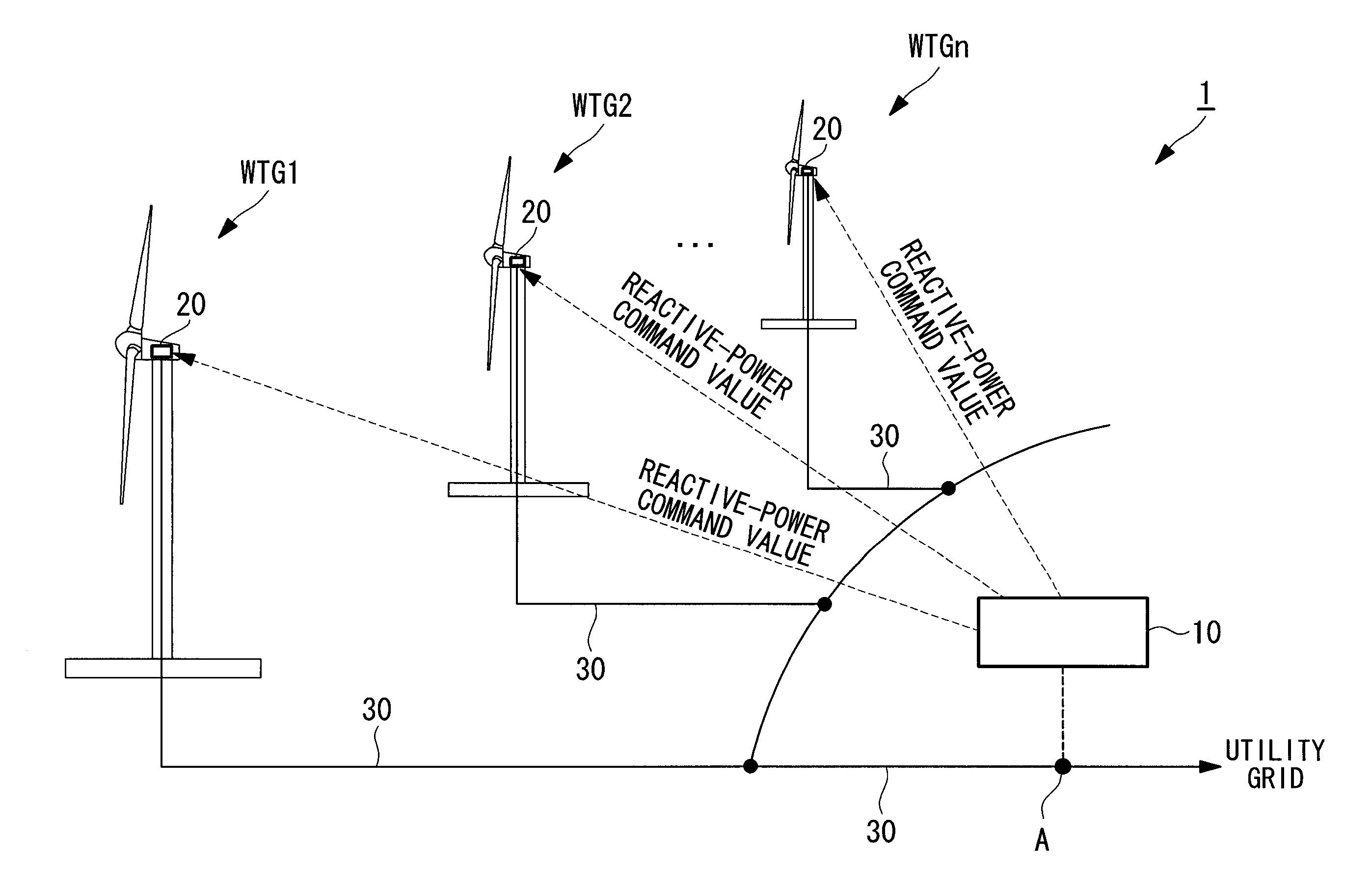
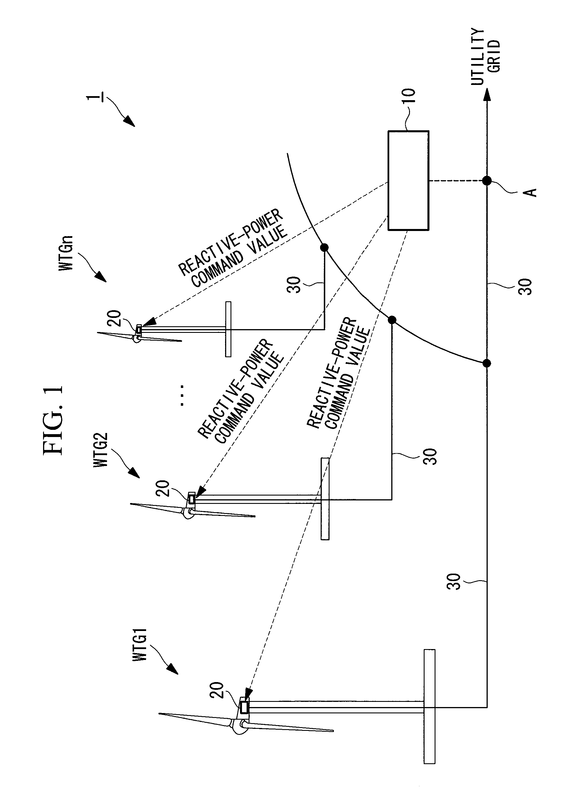
[0034]FIG. 1 is a block diagram showing the entire configuration of a wind turbine generator system according to this embodiment. As shown in FIG. 1, a wind turbine generator system 1 includes a plurality of wind turbines WTG1, WTG2, . . . , WTGn (hereinafter denoted simply by the reference sign “WTG” when all wind turbines are referred to and denoted by the reference signs “WTG1”, “WTG2”, etc. when the individual wind turbines are referred to) and a central controller 10 for providing control commands to the individual wind turbines WTG. In this embodiment, all wind-power generators WTG are variable-speed wind turbines.

[0035]Each wind turbine WTG includes a generation system 20. The generation system 20 includes, as the main configuration thereof, for example, a generator, a variable-frequency converter excitation system capable of controlling the active power and the reactive power of the generator, and a wind turbine controller for providing a power command value to the variable-...

second embodiment

[0065]Next, a second embodiment of the present invention will be described using FIG. 4.

[0066]While the case where all wind turbines are variable-speed wind turbines has been described in the first embodiment described above, the case where some wind turbines are fixed-speed wind turbines will be described in this embodiment.

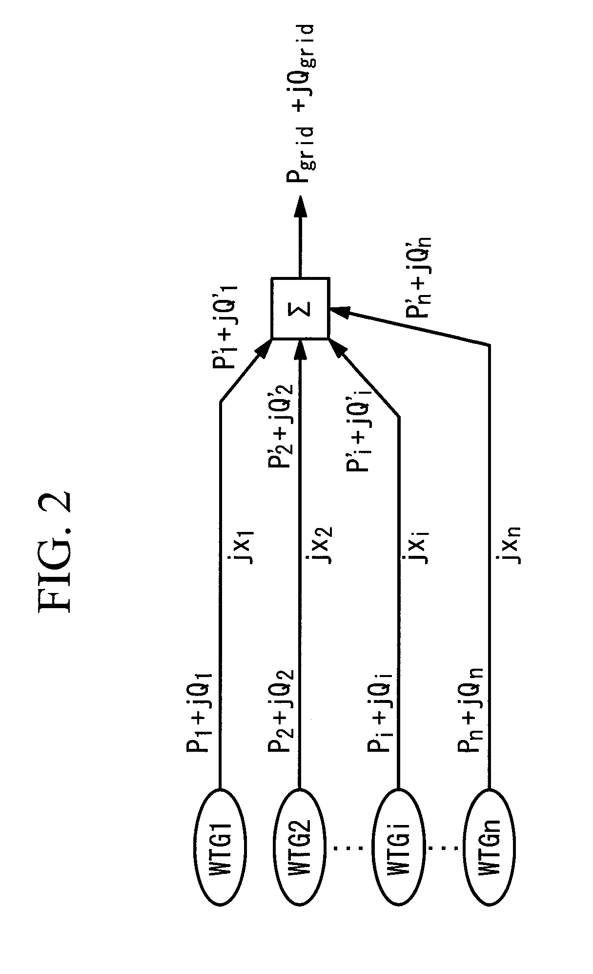
[0067]A wind turbine generator system according to this embodiment includes at least one fixed-speed wind turbine and at least one variable-speed wind turbine. As shown in FIG. 4, for example, the first to i-th wind turbines are variable-speed wind turbines, whereas the i+1-th to n-th wind turbines are fixed-speed wind turbines. In this case, first, the reactive powers Qi at the output ends of the wind turbines and the reactive powers Qi′ at the interconnection node A are determined by power flow calculation based on the same procedure as in the first embodiment described above.

[0068]Subsequently, the sums of the reactive powers of the fixed-speed wind turbines ...


PUM


Abstract

An object is to improve the accuracy of reactive power adjustment. Reactive-power command values corresponding to individual wind turbines are determined by correcting a predetermined reactive-power command value for an interconnection node A using reactive power correction levels set for the individual wind turbines.

Description

TECHNICAL FIELD[0001]The present invention relates to wind turbine generator systems and operation control methods therefor.BACKGROUND ART[0002]For power control at an interconnection node in a wind farm, conventionally, as disclosed in, for example, Patent Citations 1 and 2, it is suggested that a central controller transmit a uniform reactive power command to individual wind turbines so that the individual wind turbines control generators based on the reactive power command.[0003]Patent Citation 1:[0004]U.S. Pat. No. 7,166,928, specification[0005]Patent Citation 2:[0006]U.S. Pat. No. 7,224,081, specificationDISCLOSURE OF INVENTION[0007]Recently, there has been a demand for increased voltage stability of utility grids, and further stabilization of the voltage at an interconnection node is required accordingly. The conventional technique described above, however, has a problem in that the power at the interconnection node cannot be efficiently stabilized because a uniform reactive p...

Claims


Application Information

Patent Timeline
IPC IPC(8): H02P9/00
CPCF03D7/0284Y02E10/723F03D7/048H02P2201/15H02J3/16H02P23/26H02J2310/18H02J2300/28H02J3/381Y02E10/76Y02E10/72Y02E40/30H02J3/50
Inventor ARINAGA, SHINJIMATSUSHITA, TAKATOSHIWAKASA, TSUYOSHISHIBATA, MASAAKIYASUGI, AKIRA
Owner MITSUBISHI HEAVY IND LTD
Why Eureka
Try Eureka