Heat Exchange and Cooling Systems

a technology of heat exchange and cooling system, applied in the field of heat transfer, can solve the problems that the increased capital expenditure of such a system is usually limited to 1, and the increased capital expenditure of such a system is not justified by the corresponding performance gain

Active Publication Date: 2011-05-19
PAX SCI
View PDF102 Cites 10 Cited by
  • Summary
  • Abstract
  • Description
  • Claims
  • Application Information

AI Technical Summary

Problems solved by technology

As a result, the COP of such systems is usually limited to 1.
While water heating systems could theoretically be devised utilizing certain operating principles of

Method used


Image

  • Heat Exchange and Cooling Systems
  • Heat Exchange and Cooling Systems
  • Heat Exchange and Cooling Systems

Examples


Embodiment Construction

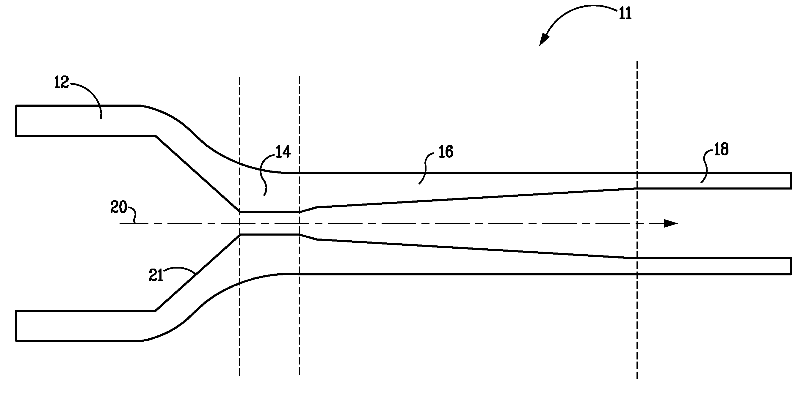
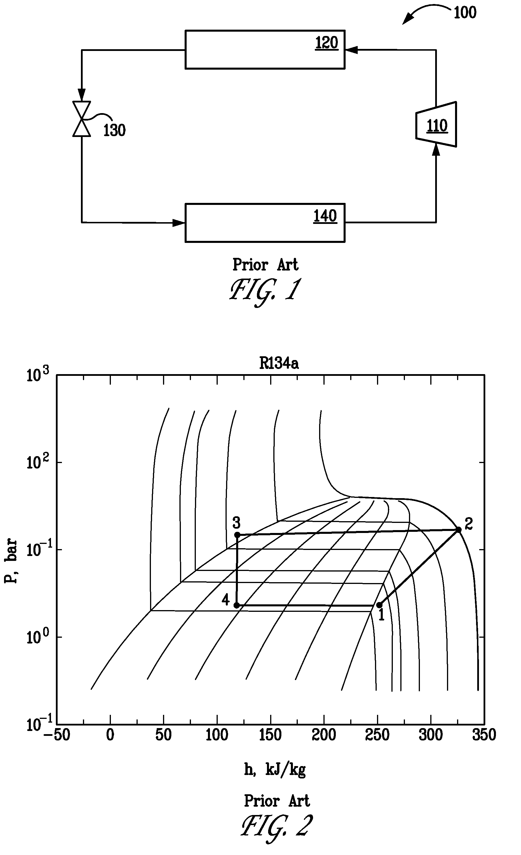
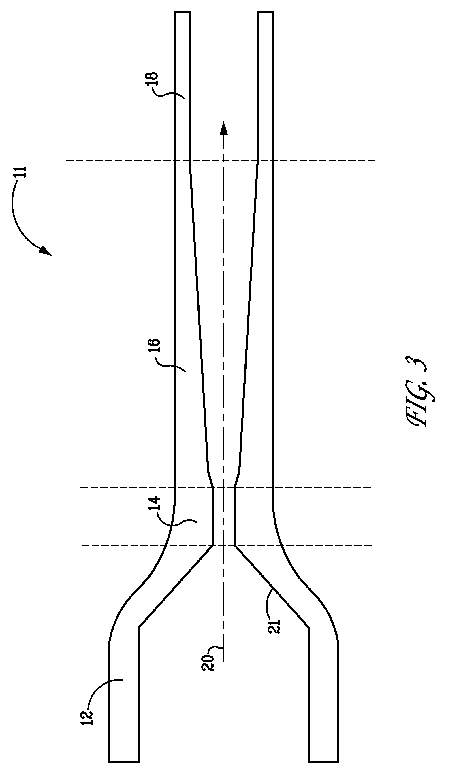
In contrast to the prior art systems of FIGS. 1 and 2, various embodiments of the present invention may rely upon cavitation for its refrigeration cycle. Through inertial cavitation, bubbles of vapor may form in regions of a flowing liquid where the pressure is reduced below the vapor pressure. This may be especially true where the dynamic pressure is rapidly reduced.

Cavitation is generally regarded as a problem as it results in turbulence, wasted energy, and a shock wave caused when the bubbles collapse and return to the liquid phase. Cavitation can cause corrosion of mechanical items such as propellers and pipes. Engineers generally go to considerable lengths to avoid or minimize cavitation. In the present context, however, inertial cavitation may be used to provide a refrigeration cycle for use in various HVAC and heat transfer applications. Cavitation may include, but is not limited to, the creation of vapor bubbles within a liquid as a result of reduced pressure regardless of w...


PUM


Abstract

A heat exchanger may be associated with a heat transfer system to promote flow of heat energy from a heat source to a multi-phase fluid. The heat exchanger may be associated with an expansion portion. The fluid may be a refrigerant to which nano-particles may be added. Embodiments of the present invention may be implemented in an air-conditioning system as well as a water heating system.

Description

BACKGROUND OF THE INVENTION1. Field of the InventionThe present invention generally relates to heat transfer including the transportation of heat energy. More specifically, the present invention is related to heating, ventilation, and air conditioning (HVAC) applications, especially liquid heating and cooling.2. Description of the Related ArtThere are many applications where it is desirable to move heat energy. For example, in the field of air-conditioning, heat energy is moved either out of or into a body of air within a building, vehicle, or other enclosed space. Such systems generally operate in the context of the co-efficient of performance (COP)—the ratio of the energy gained by the body of air relative to the energy input. Many air conditioning systems operate with a COP of 2 to 3.5.Water heating also invokes various heat transportation applications. Many water heating systems rely upon the direct application of heat energy to a body of water in order to raise temperature. As ...

Claims


Application Information

Patent Timeline
IPC IPC(8): F25B9/02
CPCF24J3/006F28D21/00F24V40/10
Inventor HARMAN, JAYDEN DAVIDGIELDA, THOMAS
Owner PAX SCI
Why Eureka
Try Eureka