Abutting apparatus of spring configuration machine

a technology of configuration machine and abutting apparatus, which is applied in the direction of wire springs, domestic applications, other domestic objects, etc., can solve the problem of manufacturing more complicated springs with 3-d configuration, and achieve the effects of enhancing the flexibility of the spring configuration process, enhancing the variability of locations and angles, and accurate positioning

Inactive Publication Date: 2011-05-19
NUCOIL IND
View PDF9 Cites 8 Cited by
  • Summary
  • Abstract
  • Description
  • Claims
  • Application Information

AI Technical Summary

Benefits of technology

[0011]Compared with the prior arts, the invention has achieved the following functions. Firstly, the drawback of the spring configuration machines according to the prior arts—the abutting apparatus can only be adjusted by a linear movement in a single direction—can be overcome by a 2-D movement in vertical and horizontal directions, so it is convenient to adjust the positions of the abutting assemblies relative to the machine platform and the spring wire feeding axle to enhance the flexibility in the spring configuration process. Secondly, since the pair of abutting assemblies are moved independently and simultaneously to make many directions of movement, more complicated spring with 3-D configuration can be manufactured. Thirdly, the first and second transmission mechanisms can enhance the variability of the locations and angles of the movement of the abutting assemblies. Fourthly, since the first and second axial transmission mechanisms are moved in a linear motion, a more accurate positioning can be achieved and it is easier in terms of operation. Finally, the pair of abutting assemblies can be respectively and independently controlled to move by using a computer, so the flexibility in manufacturing the spring can be enhanced significantly and the difficulty of configuration can be also lowered down in great scale.

Problems solved by technology

Secondly, since the pair of abutting assemblies are moved independently and simultaneously to make many directions of movement, more complicated spring with 3-D configuration can be manufactured.

Method used


Image

  • Abutting apparatus of spring configuration machine
  • Abutting apparatus of spring configuration machine
  • Abutting apparatus of spring configuration machine

Examples


Embodiment Construction

[0025]In cooperation with attached drawings, the technical contents and detailed description of the present invention are described thereinafter according to a number of preferable embodiments, not used to limit its executing scope. Any equivalent variation and modification made according to appended claims is all covered by the claims claimed by the present invention.

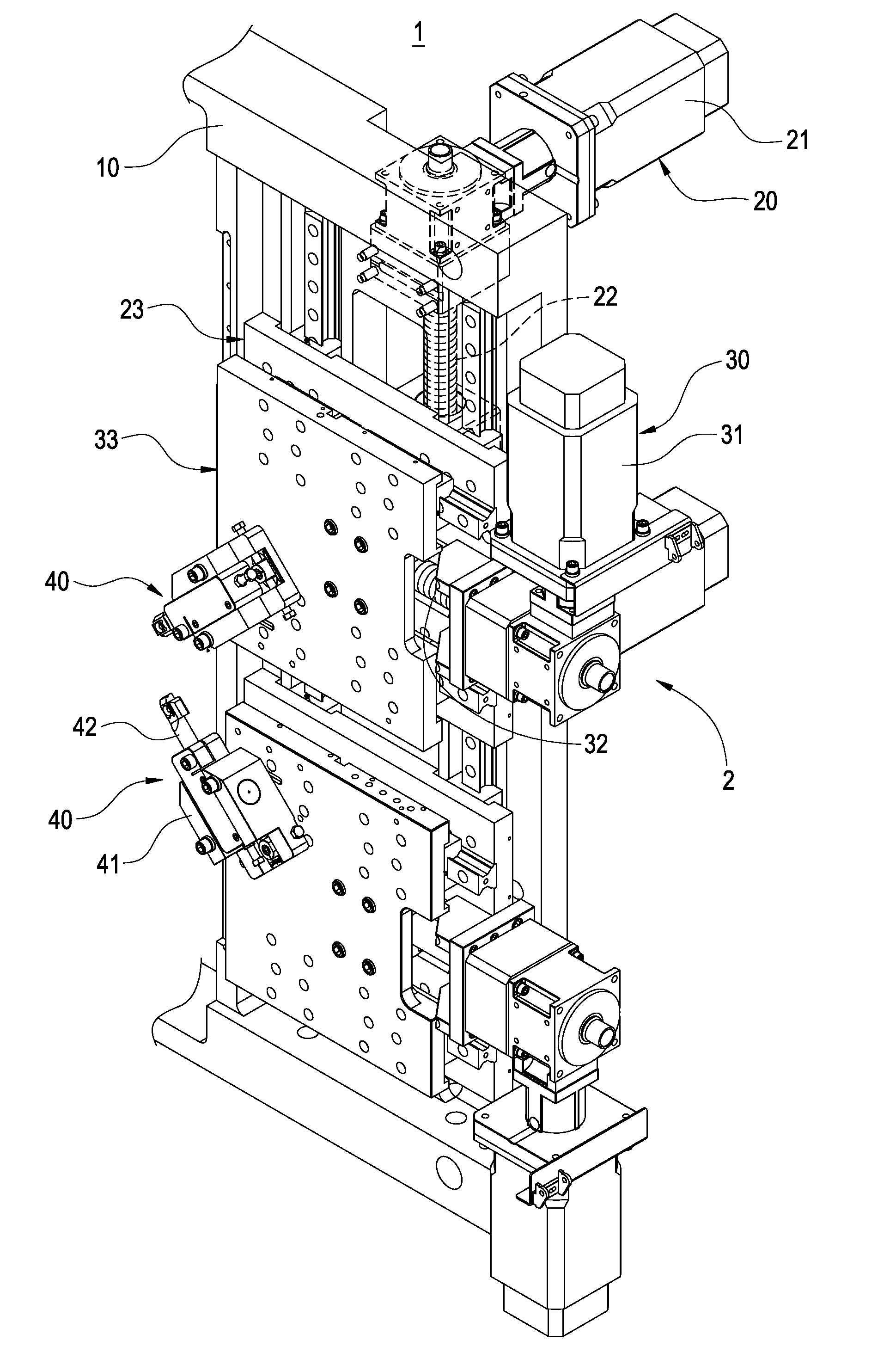
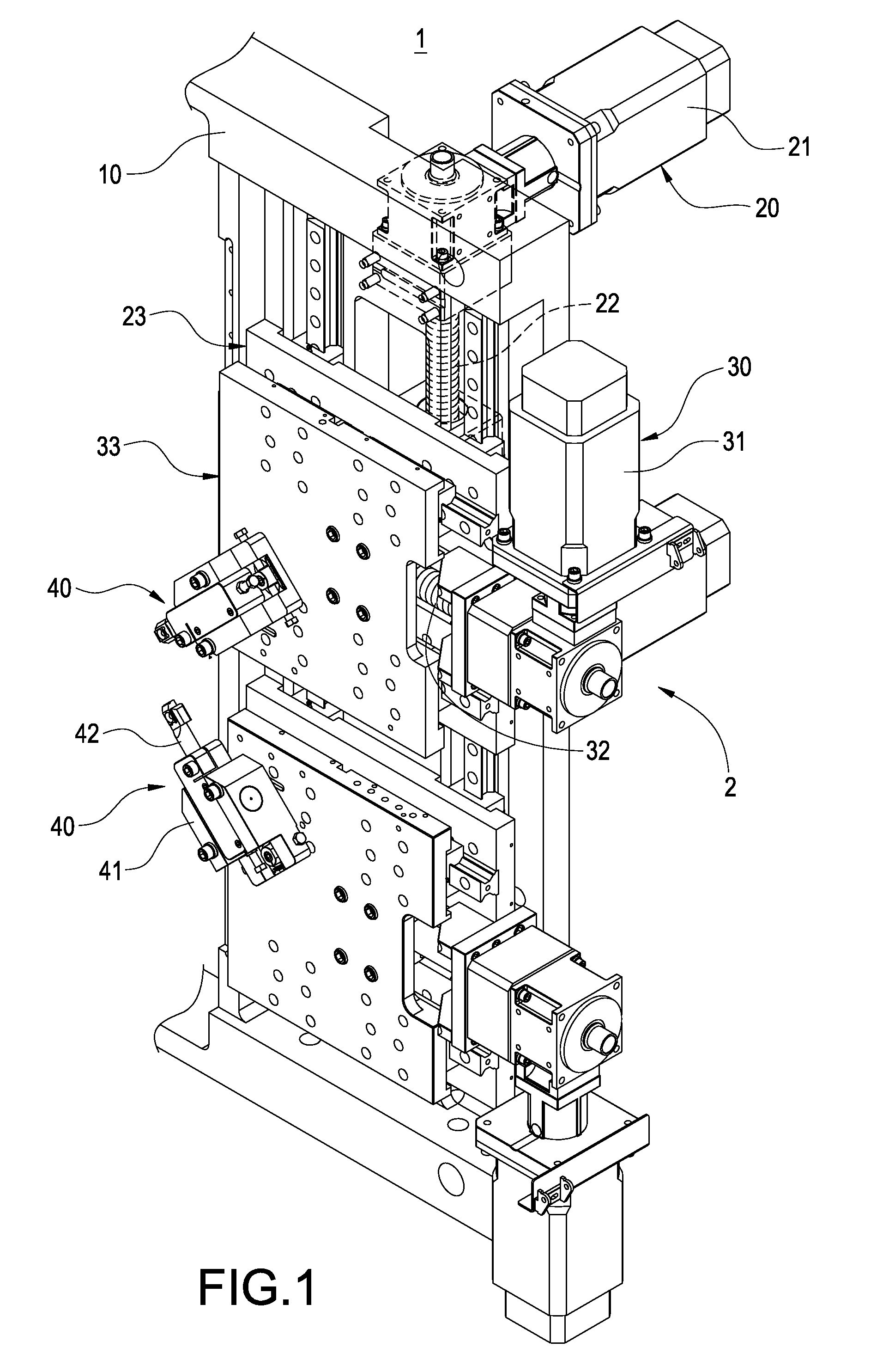
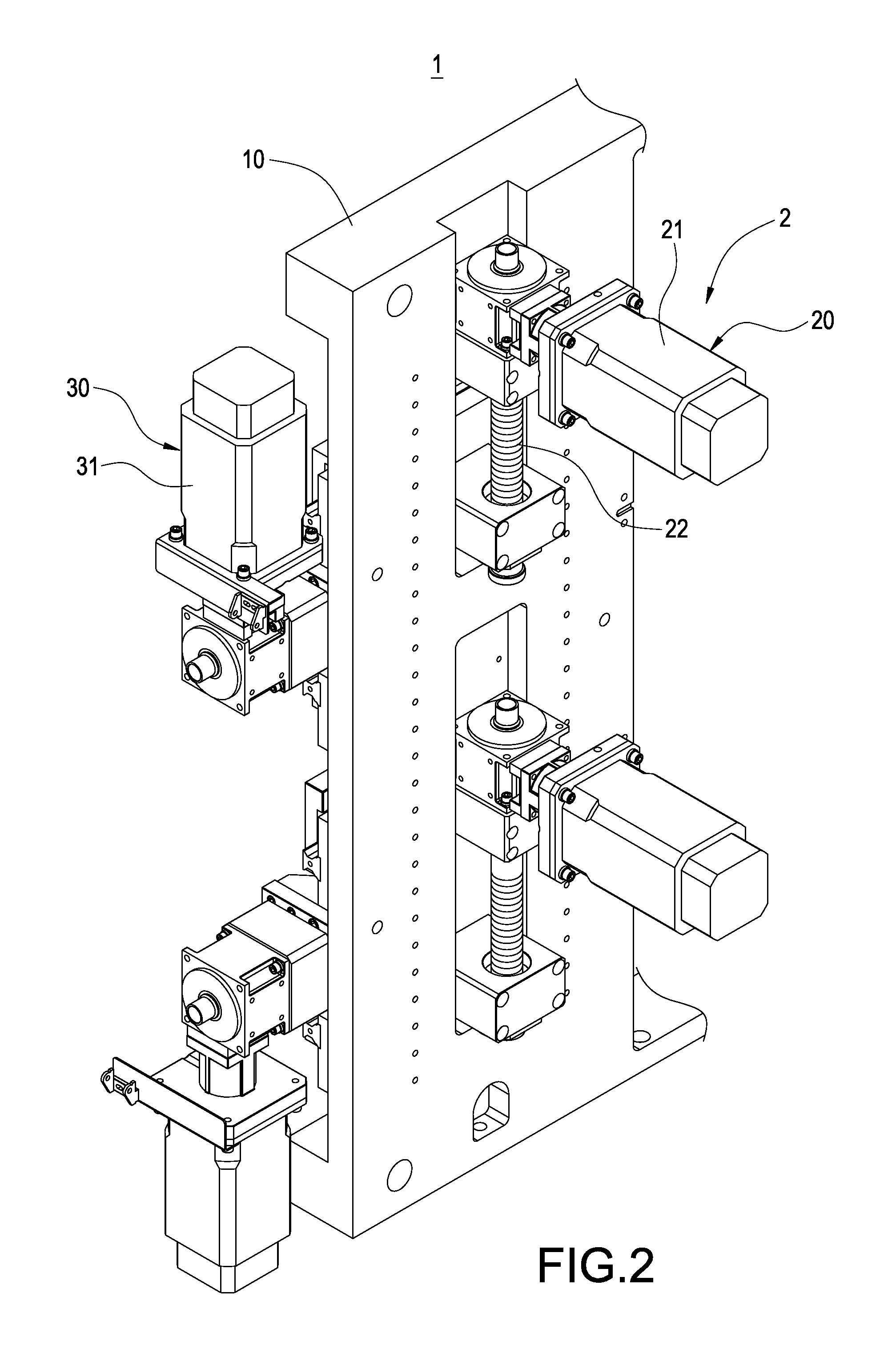
[0026]Please refer to FIG. 1 and FIG. 2, which respectively are a perspective outer view of the invention and a perspective outer view from another viewing angle of the invention. The invention is to provide an abutting apparatus 2 of spring configuration machine, in which the spring configuration machine 1 has a machine platform 10 and a spring wire feeding axle 11 (as shown in FIG. 8). The abutting apparatus 2 includes a pair of first axial transmission mechanisms 20, a pair of second axial transmission mechanisms 30 and a pair of abutting assemblies 40.

[0027]The pair of first axial transmission mechanisms 20 are res...


PUM

PropertyMeasurementUnit
degree of freedomaaaaaaaaaa
lifting angleaaaaaaaaaa

Abstract

An abutting apparatus of spring configuration machine which has a machine platform includes a first and second axial transmission mechanisms and an abutting assembly. The first axial transmission mechanism includes a first actuator, a first lead screw and a first sliding seat screwed with the first lead screw. The second axial transmission mechanism includes a second actuator fixed to the first sliding seat, a second lead screw driven to rotate by the second actuator and a second sliding seat screwed with the second lead screw and linearly moved relatively to the first sliding seat. Via the first and second axial transmission mechanisms, the abutting assembly fixed to the second sliding seat can make a 2-D movement in vertical and horizontal directions relative to the machine platform, such that the degree of freedom to adjust the abutting assembly can be enhanced significantly.

Description

BACKGROUND OF THE INVENTION[0001]1. Field of the Invention[0002]The present invention in general relates to an abutting apparatus, in particular, to an abutting apparatus of spring configuration machine.[0003]2. Description of Prior Art[0004]Accordingly, common spring configuration machines all have abutting apparatus adapted for abutting wire into configuration of spring. During the process of configuring a spring, wire is fed into the spring configuration machine via a feeding mechanism; in the meantime, an abutting apparatus is adapted for curling the wire into a spring; finally, a cutting knife apparatus is applied to cut off the wire to complete the procedure of configuring a spring. During the process, the function of the abutting apparatus is to curl a linear wire into a curled spring. According to common practices, a spring configuration machine usually has two abutting assemblies arranged corresponding to each other at two sides thereof. Adjusting the positions of these two...

Claims


Application Information

Patent Timeline
Patent Type & Authority Applications(United States)
IPC IPC(8): B21F45/00
CPCB21F35/00B21F3/02
Inventor WU, DAVID
Owner NUCOIL IND
Why Eureka
Try Eureka