
Battery Power System for Plug In Hybrid Tractor Trailers

a hybrid and battery power technology, applied in the field of plug-in hybrid and electric tractor trailers, can solve the problems of large size and bulk of battery power packs, and the use of battery power for the principal motive force of heavy duty transportation, such as tractor trailers, is much more problematic, and achieves the effect of increasing the capacity of large-capacity battery sources, efficient charging, and high capacity

Inactive Publication Date: 2011-05-19
CONTROL MODULE INDUSTRIES
View PDF7 Cites 111 Cited by
  • Summary
  • Abstract
  • Description
  • Claims
  • Application Information

AI Technical Summary

Benefits of technology

Briefly stated, a battery power system for plug in hybrid or electric tractor trailers efficiently addresses the high power requirements for heavy duty transport by plug in hybrid or electric tractor trailers and the efficient recharging of a high capacity battery supplies adapted for usage in plug in hybrid or electric vehicles. The system provides for increased capability of large capacity battery sources by mounting a battery module to the carriage of the trailer. The battery module can then be connected to the plug in hybrid or electric cab to supply electric power to the electric motor of the cab. The power module in the trailer can also be disconnected from the plug in hybrid or electric cab so that the cab may be decoupled from the trailer and employed for other purposes such as retrieving another trailer.
In addition, the battery module may be efficiently charged while the trailer is being unloaded and / or loaded at a loading dock. The system allows for the plug in hybrid or electric cab to be employed in an efficient manner on its own battery power without the trailer. For conditions in which the plug in hybrid or electric cab and trailer are connected for transport, the enhanced power capacity provided by the battery module of the trailer efficiently matches the high power demand for transport loads over significant distances with a corresponding high capacity power supply.

Problems solved by technology

The use of battery power for the principal motive force for heavy duty transport, such as tractor trailers, is much more problematic.
The size and bulk of the battery power packs can be extremely large.

Method used


Image

  • Battery Power System for Plug In Hybrid Tractor Trailers
  • Battery Power System for Plug In Hybrid Tractor Trailers
  • Battery Power System for Plug In Hybrid Tractor Trailers

Examples


Embodiment Construction

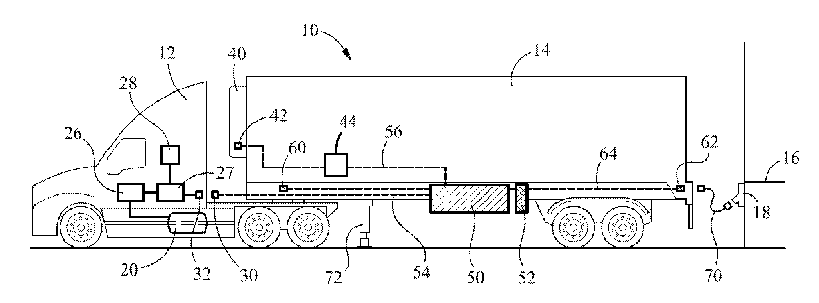
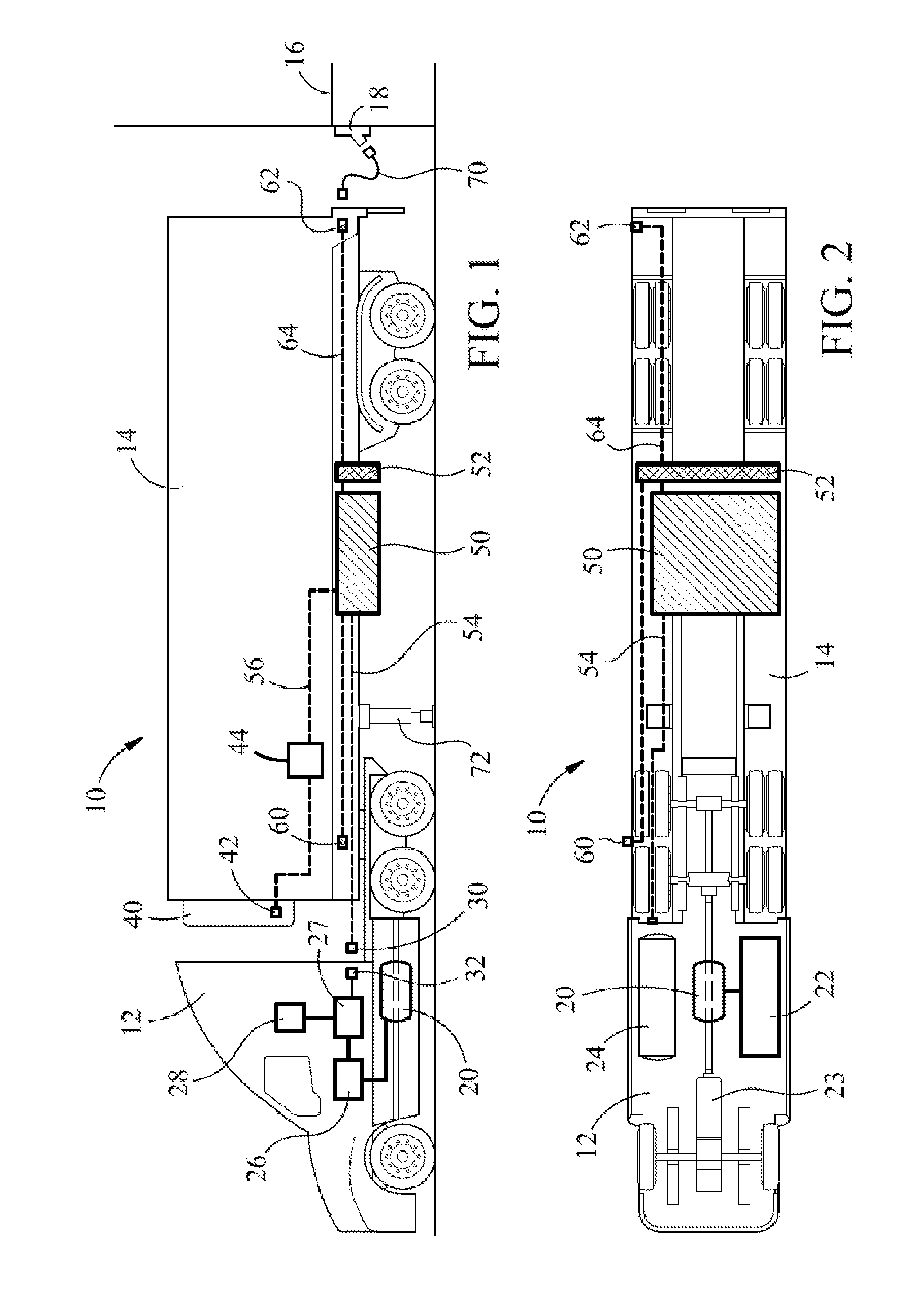
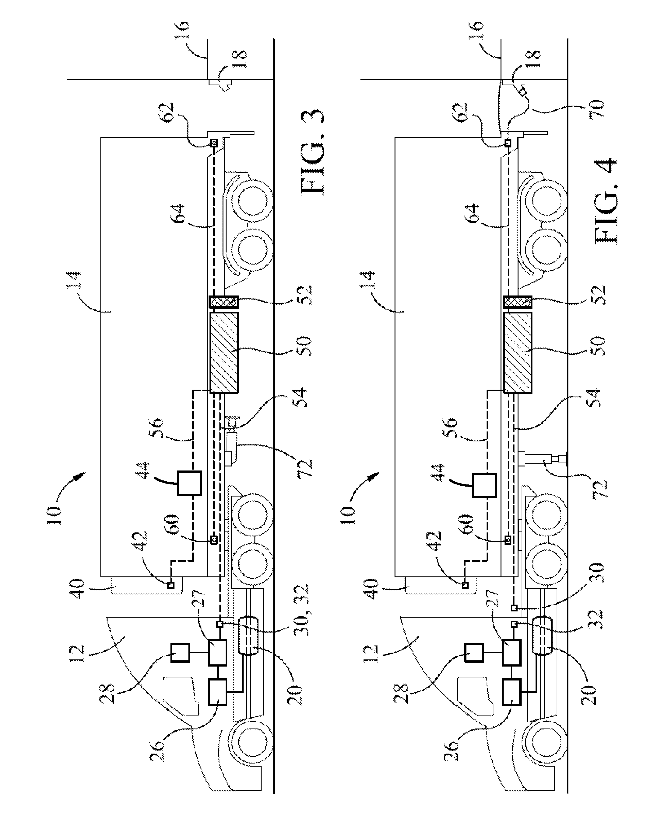
With reference to the drawings wherein like numerals represent like parts throughout the several figures, a plug in hybrid tractor trailer which employs battery power as well as an internal combustion engine for the motive power is generally designated by the numeral 10. The plug in hybrid tractor trailer comprises a plug in hybrid tractor or cab 12 which couples with the trailer 14. In FIG. 1, the tractor trailer is illustrated as parked at a loading dock 16 which also has a power outlet 18. It should be appreciated that the cab 12 and trailer 14 are intended to be representative of various possible types and configurations. The cab 12, in some embodiments, may be powered solely by electricity and not employ an internal combustion engine.

The plug in hybrid cab 12 employs an induction drive motor 20 which obtains power from an onboard battery module 22. In one embodiment, the battery module is disposed opposite the fuel tank 24 for the internal combustion engine. A voltage converter...


PUM


Abstract

A battery power system for a plug-in hybrid or electric tractor trailer employs a battery module which is carried by the trailer. A cable communicates with the battery module and connects with a connector on the cab for supplying power to power the electric motor of the cab. The cab can be disconnected from the trailer while the battery module on the trailer is charged. The cab can then be driven by the electric motor powered by the battery supply of the cab.

Description

BACKGROUNDThis disclosure relates generally to electric and plug in hybrid and electric vehicles. More particularly, this disclosure relates to plug in hybrid and electric tractor trailers and methods for adding batteries to new and existing tractors and trailers.In vehicles and recharging methods to which the disclosure relates, a vehicle derives its motive power from an electrical battery source and also employs an internal combustion engine to provide an auxiliary source of motive power. A number of facilities and techniques have been proposed for periodically charging the battery power supply while the vehicle is in an idle state. The use of battery power for the principal motive force for heavy duty transport, such as tractor trailers, is much more problematic. In order to be effective, the battery power sources must provide relatively large quantities of power. The size and bulk of the battery power packs can be extremely large. It is also necessary to provide a highly efficie...

Claims


Application Information

Patent Timeline
IPC IPC(8): B60K1/04H02J7/00B60L11/18
CPCB60K1/00B60Y2400/61B60K2001/001B60K2001/0438B60K2001/0444B60L11/1816B60L11/1877B60L2200/28B60L2200/36B60Y2200/145B60Y2200/147Y02T10/7005Y02T10/705Y02T90/14Y02T90/16B60K1/04B60L50/66B60L53/14Y02T10/70Y02T10/7072
Inventor BIANCO, JAMES S.
Owner CONTROL MODULE INDUSTRIES
Learn More