Gas spring and gas damper assembly and method

a technology of gas springs and dampers, applied in the field of spring devices, can solve the problems of increased gas pressure, less comfort for vehicles, increased spring mass, etc., and achieve the effect of dissipating kinetic energy, dissipating kinetic energy, and reducing the volume of the spring chamber

Active Publication Date: 2011-05-19
FIRESTONE IND PROD COMPANY
View PDF72 Cites 66 Cited by
  • Summary
  • Abstract
  • Description
  • Claims
  • Application Information

AI Technical Summary

Benefits of technology

[0014]One example of a method of operating a gas spring and gas damper assembly in accordance with the subject matter of the present disclosure can include providing a first end member and a second end member with the second end member including a damping chamber wall that at least partially defines a damping chamber. The method can also include providing a damper piston received within the damping chamber such that the damping chamber has first and second portions on opposing sides of the damper piston, and forming a gas damper by operatively connecting the damper piston to the first end member such that relative displacement of the first and second end members results in displacement of the damper piston within the damping chamber. The method can further include forming a spring chamber about the gas damper from a first flexible wall secured between the first and second end members. The method can also include transferring pressurized gas between the spring chamber and the first portion of the damping chamber to dissipate kinetic energy acting on the gas spring and gas damper assembly.
[0015]Another example of a method of operating a gas spring and gas damper assembly in accordance with the subject matter of the present disclosure can include providing a first end member and a second end member with the first end member including a side wall at least partially defining an end member cavity. The method also includes forming a gas damper from a damper piston received within the end member cavity such that the end member cavity has first and second on opposing sides of the damper piston by operatively connecting the damper piston to the second end member such that relative displacement of the first and second end members results in displacement of the damper piston within the end member cavity along the side wall. The method further includes forming a spring chamber about the damper from a first flexible wall secured along the first and second end members. The method also includes transferring pressurized gas between the spring chamber and the first portion of the end member cavity to dissipate kinetic energy acting on the gas spring and gas damper assembly.
[0016]A further example of a method of operating a gas spring and gas damper assembly in accordance with the subject matter of the present disclosure can include providing a first end member, a second end member, and a third end member. The second end member including an end wall and a side wall that at least partially defines an inner cavity of the second end member. The end wall includes at least a first passage and a second passage that extends therethrough. The third end member is at least partially received within the inner cavity of the second end member. The method also includes securing a first flexible wall between the first end member and the second end member to at least partially define a spring chamber in fluid communication with the inner cavity of the second end member through the first passage. The method further includes securing a second flexible wall between the second end member and the third end member to separate the inner cavity into a first chamber in fluid communication with the spring chamber through the first passage and a second chamber in fluid communication with an external atmosphere. The method also includes interconnecting the first end member and the third end member such that: (1) upon movement of the first and second end members away from one another, a volume of the spring chamber increases and a volume of the first chamber decreases; and (2) upon movement of the first and second end members toward one another, the volume of the spring chamber decreases and the volume of the first chamber increases. The method further includes transferring pressurized gas between the spring chamber and the first chamber during the movements in (1) and (2) and thereby dissipating kinetic energy acting on the gas spring and gas damper assembly.

Problems solved by technology

That is, it is well understood in the art that the use of a spring element having a higher spring rate (i.e. a stiffer spring) will transmit a greater magnitude of inputs (e.g., road inputs) to the sprung mass and that, in some applications, this could undesirably affect the sprung mass, such as, for example, by resulting in a rougher, less-comfortable ride of a vehicle.
One difficulty with known gas spring and gas damper assemblies involves balancing spring rate with damping performance.
However, this increased gas pressure can, in some cases, have an undesirable affect on the spring rate of the gas spring, such as by undesirably increasing the spring rate in applications in which a lower spring rate is desired, for example.

Method used


Image

  • Gas spring and gas damper assembly and method
  • Gas spring and gas damper assembly and method
  • Gas spring and gas damper assembly and method

Examples


Embodiment Construction

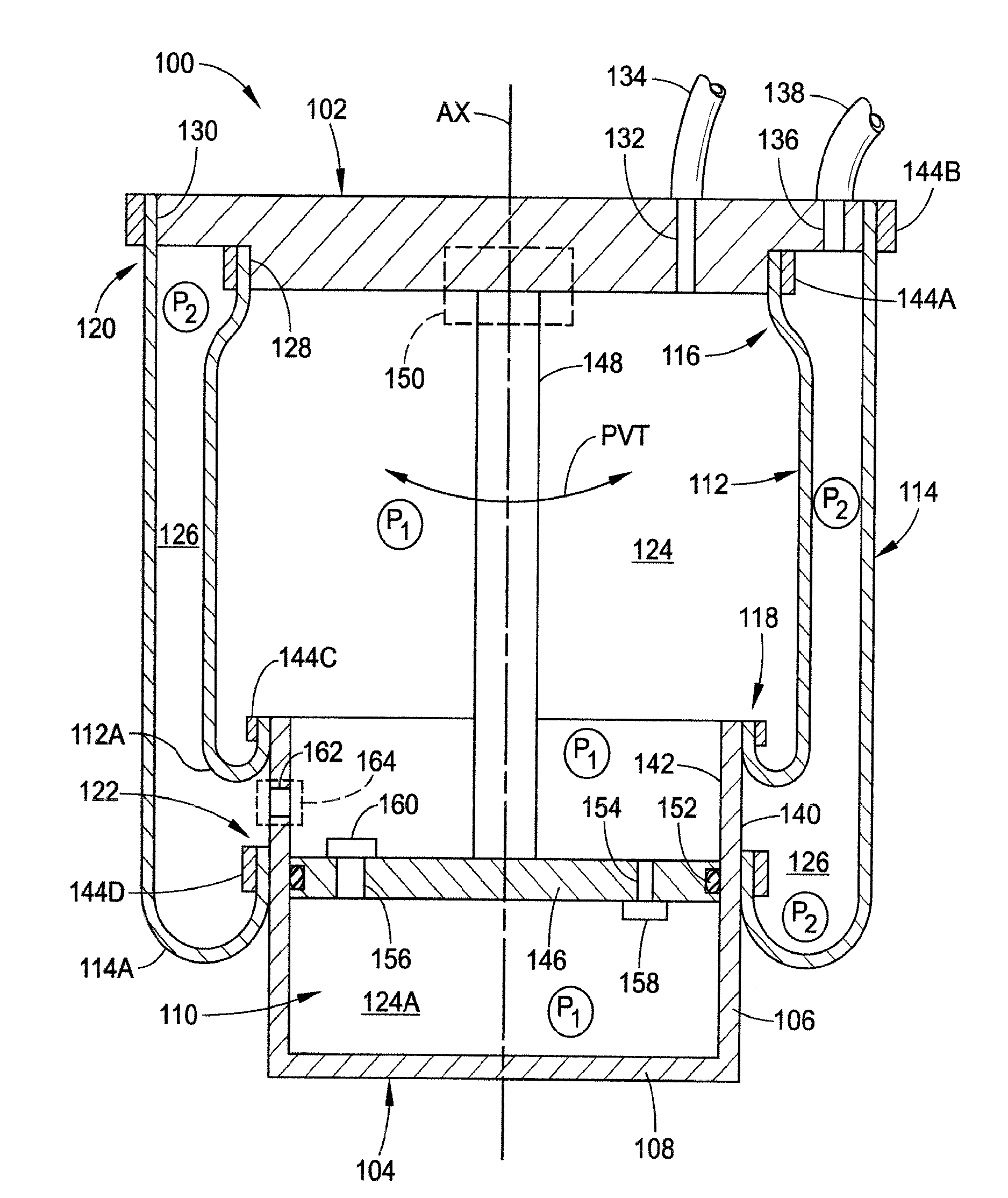
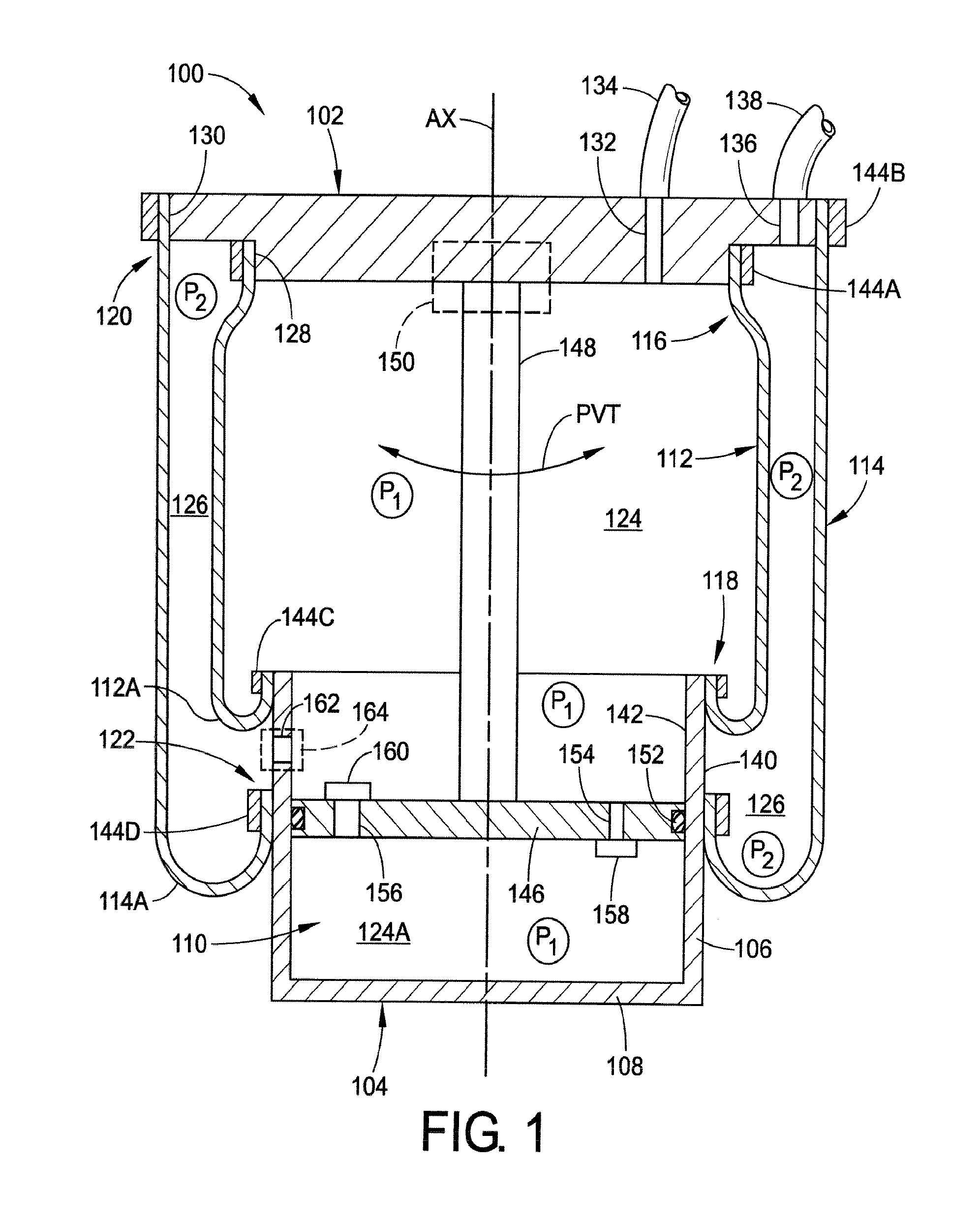
[0025]Turning now to the drawings, wherein the showings are for the purpose of illustrating exemplary embodiments of the subject matter of the present disclosure only and not for the purposes of limiting the same, FIG. 1 illustrates a gas spring and gas damper assembly 100 that includes a first or upper end member 102 and a second or lower end member 104 disposed in longitudinally-spaced relation to the first end member. Assembly 100 also includes a longitudinally-extending axis AX that extends generally between first and second end members 102 and 104. Second end member 104 includes a side wall 106 and an end wall 108 that at least partially define an end member cavity 110 within second end member 104.

[0026]Assembly 100 also includes a first or inner flexible wall 112 and a second or outer flexible wall 114, respectively. Inner flexible wall 112 is disposed circumferentially about axis AX and extends longitudinally between a first or upper end 116 and a second or lower end 118. Sim...


PUM

PropertyMeasurementUnit
pressuresaaaaaaaaaa
pressuresaaaaaaaaaa
gas pressureaaaaaaaaaa

Abstract

A gas spring and gas damper assembly includes a first end member, a second end member and a flexible wall that at least partially defines a first spring chamber therebetween. A damping chamber wall at least partially defines a damping chamber. A damper piston is received within the damping chamber and is operatively connected between the first and second end members and within the first spring chamber. A suspension system that includes a gas spring and gas damper assembly as well as a method of assembly are also included.

Description

[0001]This application claims the benefit of priority from U.S. Provisional Patent Application No. 61 / 165,781 filed on Apr. 1, 2009; U.S. Provisional Patent Application No. 61 / 140,495 filed on Dec. 23, 2008; U.S. Provisional Patent Application No. 61 / 120,719 filed on Dec. 8, 2008; and U.S. Provisional Patent Application No. 61 / 079,276 filed on Jul. 9, 2008, the subject matter of each of which is hereby incorporated herein by reference in its entirety.BACKGROUND[0002]The present disclosure broadly relates to the art of spring devices and, more particularly, to a gas spring and gas damper assembly that includes a gas spring used in combination with a gas damper, as well as a vehicle suspension system and a method of operating such a gas spring and gas damper assembly.[0003]Suspension systems, such as may be used in connection with motorized vehicles, for example, typically include one or more spring elements for accommodating forces and loads associated with the operation and use of t...

Claims


Application Information

Patent Timeline
Patent Type & Authority Applications(United States)
IPC IPC(8): B60G15/12F16F9/05
CPCB60G15/14B60G17/0521B60G2202/242B60G2202/314B60G2204/1262Y10T29/49609B60G2401/176F16F9/0472B60G15/12B60G17/00F16F9/05B60G2400/252
Inventor MOULIK, PRADIPTA N.BOUNDS, JOSEPH A.BROOKERS, GRAHAM R.
Owner FIRESTONE IND PROD COMPANY
Why Eureka
Try Eureka