Plasma source design

a technology of plasma processing and source, applied in the direction of plasma technique, electric discharge lamp, electric lighting source, etc., can solve the problems of small plasma processing window that limits the range of energy of formed gas radicals, unwanted sputtering and damage to the substrate surface, and plasma ions to bombard and possibly damage the exposed surfaces of the substrate or chamber componen

Active Publication Date: 2011-05-19
APPLIED MATERIALS INC
View PDF52 Cites 432 Cited by
  • Summary
  • Abstract
  • Description
  • Claims
  • Application Information

AI Technical Summary

Benefits of technology

[0013]Embodiments of the present invention generally provide a plasma source coupled to a processing chamber, comprising a core element having a first end, a second end and a core element central axis, a first plasma block having one or more surfaces that at least partially enclose a first annular shaped plasma generating region, wherein the first annular shaped plasma generating region is disposed around a first portion of the core element, and a coil disposed over a portion of the core element.

Problems solved by technology

Conventional plasma processing chamber designs in which the generated plasma is disposed over the substrate surface can cause unwanted sputtering and damage to the substrate surface due to the interaction of electrons and ions formed in the plasma with the substrate surface.
The formed net charge causes electrons and / or ions formed in the plasma to bombard and possibly damage the exposed surfaces of the substrate or chamber component.
However, current conventional RPS designs typically utilize microwave, capacitively coupled or inductively coupled energy sources that have a narrow plasma generating region, which will cause these devices to have a smaller than desirable plasma processing window that limits the range of energies of the formed gas radicals and gas ion that are formed in the plasma generating region of the conventional RPS device.
Thus, conventional RPS designs that have a small plasma generating region have a very limited ability to generate and / or control the energies of the formed gas radicals and / or gas ions.
Conventional RPS designs that inefficiently couple the plasma energy to the processing gasses are not currently able to meet the needs of the semiconductor processing industry.
However, it has been found that the use of a switching power supply in an RPS design is ineffective in efficiently coupling the delivered RF energy to the plasma.
However, it has been found that significant process result drift will occur when using coatings in the plasma formation region of an RPS device.
Coating problems can be especially an issue when the plasma contains oxidizing species or fluorinated species that tend to attack most commonly used metal materials.

Method used


Image

  • Plasma source design
  • Plasma source design
  • Plasma source design

Examples


Embodiment Construction

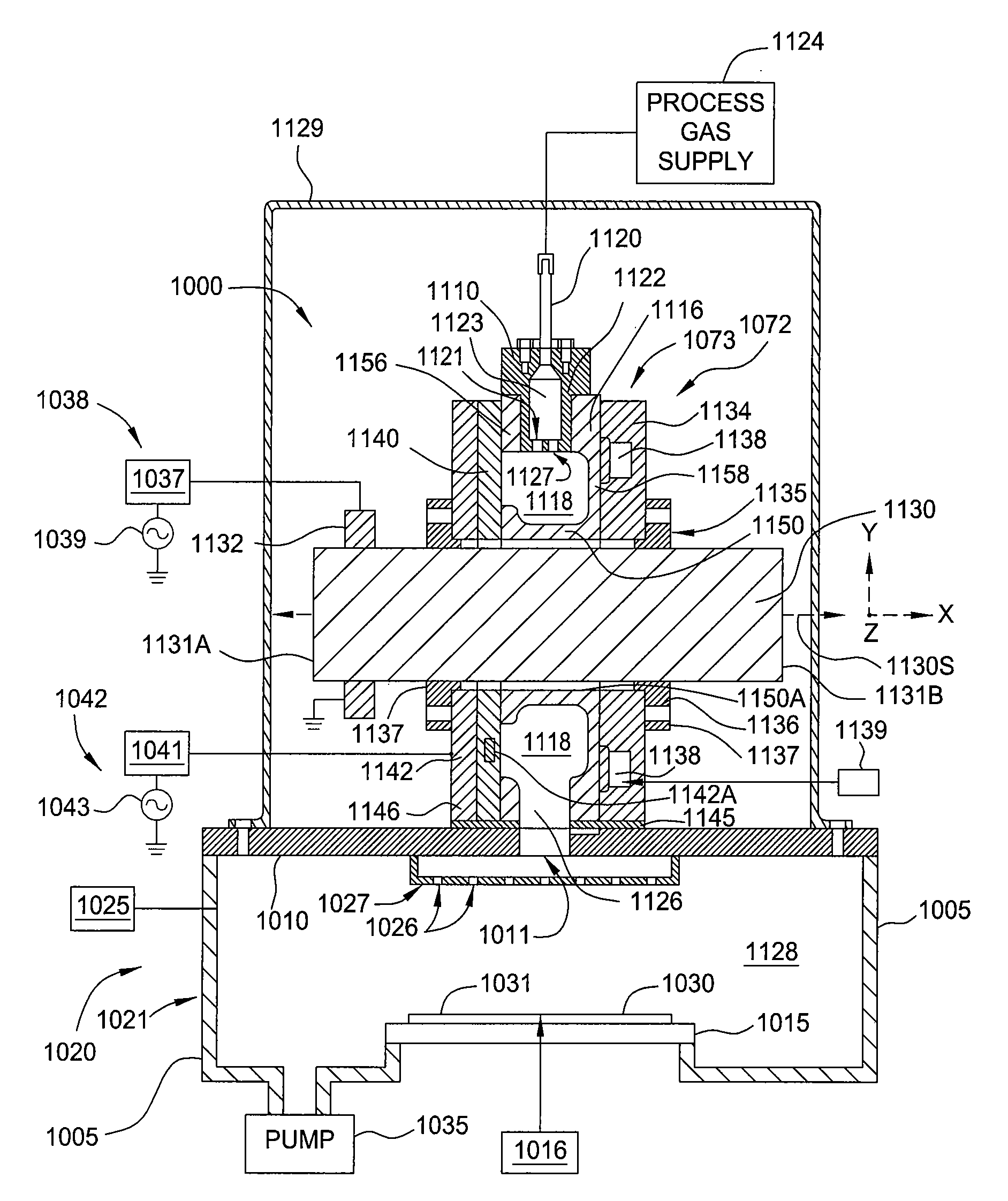
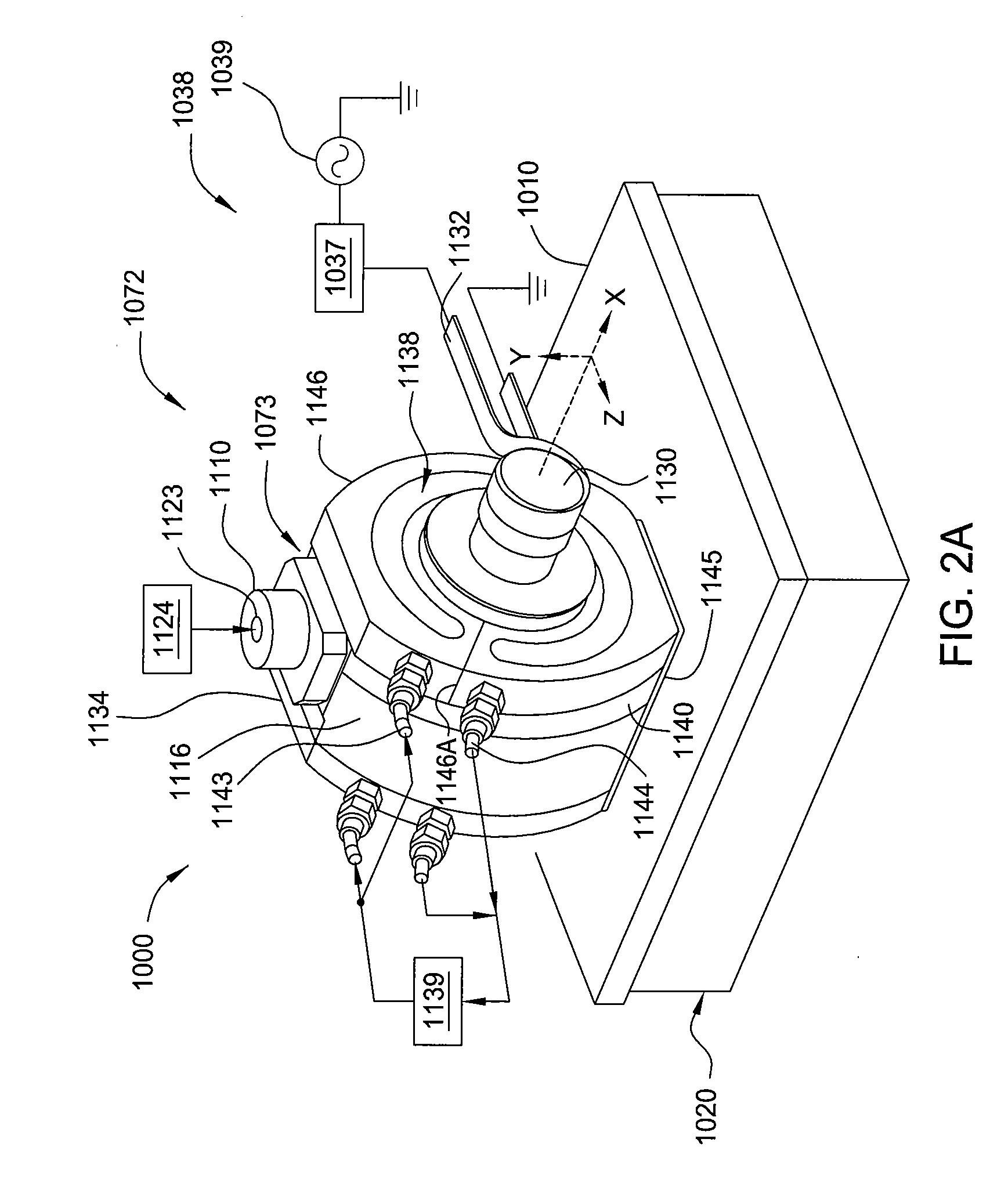
[0033]Embodiments of the present invention generally provide a plasma source apparatus, and method of using the same, that is able to generate radicals and / or gas ions in a plasma generation region that is symmetrically positioned around a magnetic core element by use of an electromagnetic energy source. In general, the orientation and shape of the plasma generation region and magnetic core allows for the effective and uniform coupling of the delivered electromagnetic energy to a gas disposed in the plasma generation region. It is believed that due to the configuration of the plasma source disclosed herein, the electromagnetic energy delivered to the magnetic core is able to more efficiently form gas radicals and / or gas ions, provide a wider process window in which to form the gas radicals and / or gas ions, and form a broader range of gas radical energies and / or ion densities than conventional plasma source designs found on the market today. In general, the improved characteristics o...


PUM


Abstract

Embodiments of the present invention generally provide a plasma source apparatus, and method of using the same, that is able to generate radicals and/or gas ions in a plasma generation region that is symmetrically positioned around a magnetic core element by use of an electromagnetic energy source. In general, the orientation and shape of the plasma generation region and magnetic core allows for the effective and uniform coupling of the delivered electromagnetic energy to a gas disposed in the plasma generation region. In general, the improved characteristics of the plasma formed in the plasma generation region is able to improve deposition, etching and/or cleaning processes performed on a substrate or a portion of a processing chamber that is disposed downstream of the plasma generation region.

Description

CROSS-REFERENCE TO RELATED APPLICATIONS[0001]This application claims benefit of U.S. provisional patent application Ser. No. 61 / 262,505, filed Nov. 18, 2009, which is herein incorporated by reference.BACKGROUND OF THE INVENTION[0002]1. Field of the Invention[0003]Embodiments of the invention generally relate to plasma processing systems and materials and apparatus for controlling plasma uniformity in plasma processing systems.[0004]2. Description of the Related Art[0005]Plasma processing chambers are regularly utilized in various electronic device fabrication processes, such as etching processes, chemical vapor deposition (CVD) processes, and other processes related to the manufacture of electronic devices on substrates. Many ways have been employed to generate and / or control the plasma density, shape, and electrical characteristics in processing chambers, such as capacitively or inductively coupled RF sources commonly used in conventional plasma chambers. For example, during a plas...

Claims


Application Information

Patent Timeline
Patent Type & Authority Applications(United States)
IPC IPC(8): H05B31/26
CPCH01J37/32357H01J37/3211H01L21/3065H05H1/46
Inventor LUBOMIRSKY, DMITRYYANG, JANG-GYOOMILLER, MATTHEWPINSON, JAYCHUC, KIEN
Owner APPLIED MATERIALS INC
Why Eureka
Try Eureka