Circuit devices and methods of providing a regulated power supply

a technology of circuit devices and power supply, applied in the direction of electric variable regulation, process and machine control, instruments, etc., can solve the problems of increasing the cost of the circuit device, increasing current, and dsp power consumption

Active Publication Date: 2011-05-19
SILICON LAB INC
View PDF24 Cites 20 Cited by
  • Summary
  • Abstract
  • Description
  • Claims
  • Application Information

AI Technical Summary

Problems solved by technology

However, the power consumption of the DSP may vary, causing current spikes that radiate electromagnetic interference (EMI) through magnetic coupling between the power input and nearby receiver circuitry.
However, large capacitors incr...

Method used


Image

  • Circuit devices and methods of providing a regulated power supply
  • Circuit devices and methods of providing a regulated power supply
  • Circuit devices and methods of providing a regulated power supply

Examples


embodiment 500

FIG. 5 is a schematic diagram of an embodiment 500 of the series regulator circuitry 102 of the circuit device 200 depicted in FIG. 2. As shown, the series regulator 110, implemented as a p-channel transistor, has a gate-source capacitance Cgs 506, a gate-drain capacitance Cgd 508 and a drain-source transconductance (gds) 504. A power supply current (i1(t)) 502 flows from the input 106 through the series regulator 110 to the regulated power supply terminal 116. A gate voltage (Vg) 510 is present on the gate of the series regulator 110.

In a typical series regulator, there is a finite reverse power supply rejection resistance due to the drain-source transconductance (gds) 504 and the gate-drain capacitance (Cgd) 506 of the series regulator 110, particularly when the series regulator is implemented as a metal oxide semiconductor field effect transistor (MOSFET) as shown. As the processing circuitry 118 produces current transients on the regulated power supply terminal 116, the supply v...

second embodiment

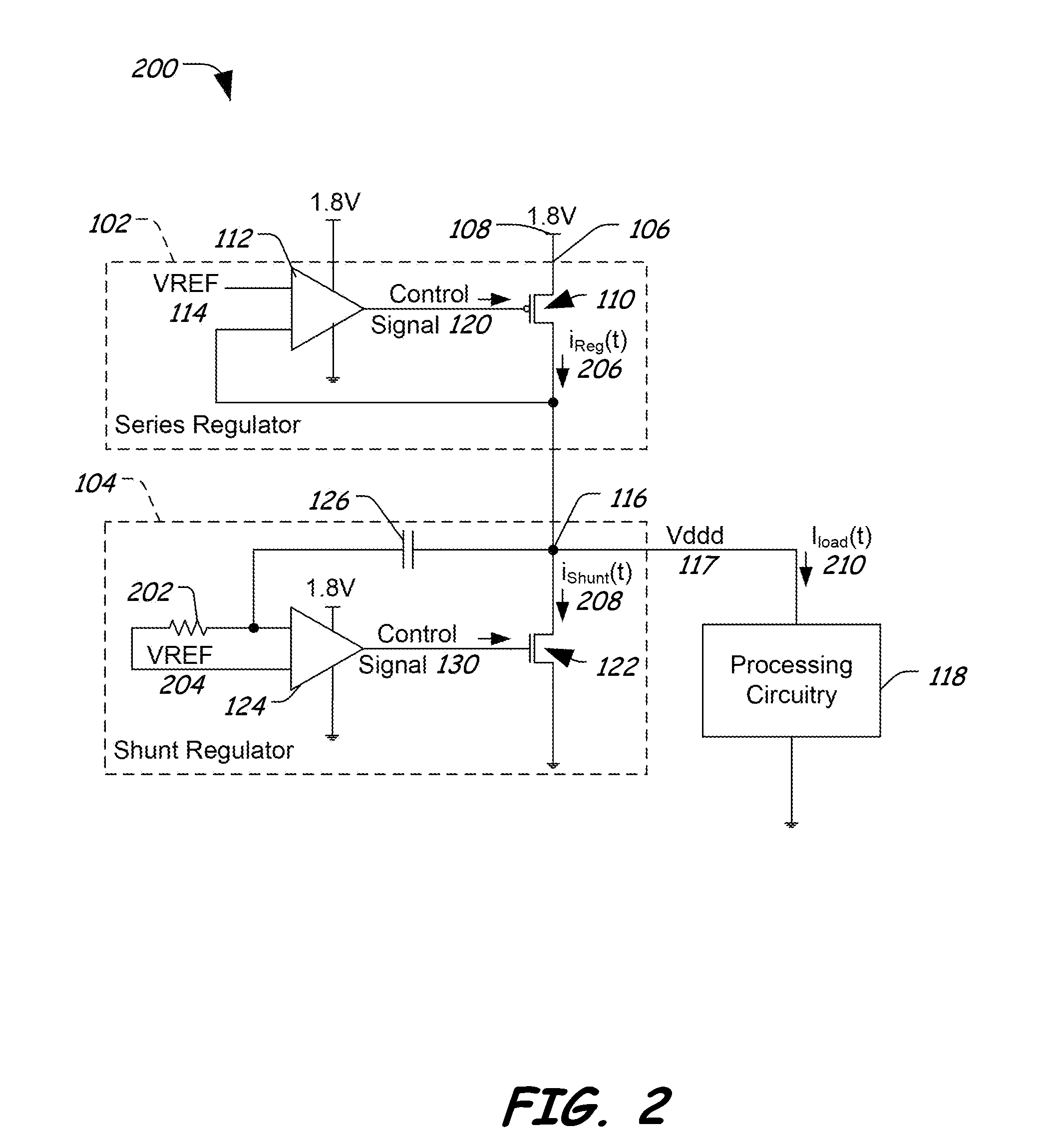
FIG. 7 is a partial schematic and partial block diagram of the circuit device 700 including series and shunt regulator circuitry configured to provide enhanced reverse power supply rejection. The circuit device 700 includes the series regulator 110 having a source terminal connected to the input 106, a gate terminal connected to an output of the amplifier 112 to receive the gate voltage (Vg) 510, and a drain terminal connected to the regulated power supply terminal 116. As previously discussed, the series regulator 110 provides a regulated current (ireg(t)) 206 to the regulated power supply terminal 116.

The circuit device 700 further includes a first MOSFET 702 having a source terminal connected to the input 106, a gate terminal connected to the gate terminal of the series regulator 110 in a common gate configuration, and a drain terminal that is connected to a drain terminal of a diode-connected transistor 704, which has a source terminal connected to ground. A gate terminal of the...


PUM


Abstract

In an embodiment, a circuit includes a regulated power supply terminal, a processing circuit coupled to the regulated power supply terminal, and a low frequency responsive circuit having a first transistor adapted to be coupled to a power source and having first circuitry configured to control current flow from the power source through the first transistor to supply a low frequency current to the regulated power supply terminal. The circuit device further includes a high frequency responsive circuit having a second transistor coupled to the regulated power supply terminal and having second circuitry configured to control the second transistor to selectively modulate high frequency current components at the regulated power supply terminal to reduce voltage variations on the regulated power supply.

Description

FIELDThe present disclosure is generally related to a circuit devices and methods of regulating a power supply.BACKGROUNDVoltage regulators are often used to provide stable power supplies for integrated circuitry, such as microprocessors, logic circuitry, digital signal processors (DSPs), and other circuitry. In an example, a DSP draws a current from the voltage regulator. However, the power consumption of the DSP may vary, causing current spikes that radiate electromagnetic interference (EMI) through magnetic coupling between the power input and nearby receiver circuitry.One approach for smoothing variations in the input current includes increasing an amount of on-chip charge storage capability, either by adding de-coupling capacitors or by increasing a capacitance of de-coupling or filter capacitors. However, large capacitors increase the cost of the circuit device. Another approach includes regulating the current, which regulation may cause the voltage supplied to the load, such ...

Claims


Application Information

Patent Timeline
IPC IPC(8): G05F1/10
CPCG05F1/618
Inventor MAY, MICHAEL ROBERT
Owner SILICON LAB INC
Why Eureka
Try Eureka