Liquid supply member, manufacturing method of liquid supply member, liquid discharge head, and manufacturing method of liquid discharge head

Active Publication Date: 2011-05-19
CANON KK
View PDF1 Cites 17 Cited by
  • Summary
  • Abstract
  • Description
  • Claims
  • Application Information

AI Technical Summary

Benefits of technology

[0011]An object of the invention is to provide a liquid supply member in which a supply path is formed with good precision and

Problems solved by technology

When the unevenness exists, small bubbles are easily generated during filling of ink and thus are obstacles to enhancement of ink filling ability.
When the ink filling ability is degraded, small bubbles easily reach the discharge port of an ink discharge part during printing,

Method used


Image

  • Liquid supply member, manufacturing method of liquid supply member, liquid discharge head, and manufacturing method of liquid discharge head
  • Liquid supply member, manufacturing method of liquid supply member, liquid discharge head, and manufacturing method of liquid discharge head
  • Liquid supply member, manufacturing method of liquid supply member, liquid discharge head, and manufacturing method of liquid discharge head

Examples


Example

First Embodiment

[0029]As a liquid discharge head according to an embodiment of the invention, an ink jet recording head for discharging ink will be described. In addition, as a liquid supply member according to the embodiment of the invention, an ink supply member for supplying ink to the ink jet recording head will be described.

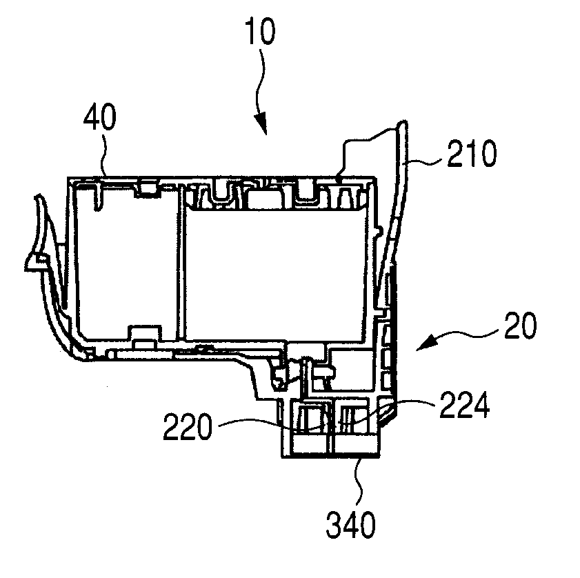
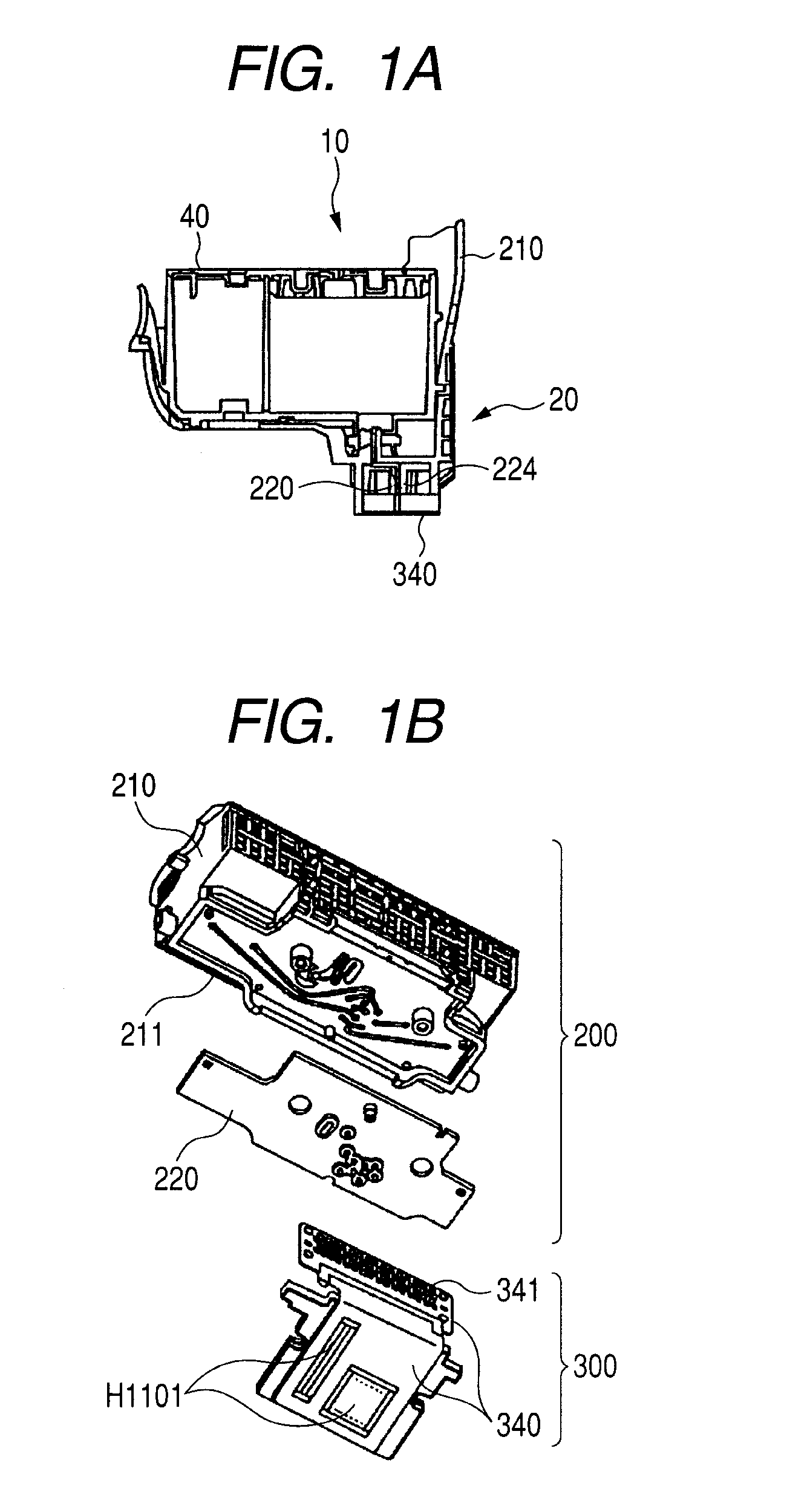
[0030]FIGS. 1A and 1B are diagrams illustrating the liquid discharge head according to the embodiment of the invention. FIG. 1A is a cross-sectional view illustrating a state where the ink jet recording head 20 as the liquid discharge head according to the embodiment of the invention is mounted to a recording head cartridge 10. FIG. 1B is an exploded perspective view of the ink jet recording head 20.

[0031]As illustrated in FIG. 1A, the recording head cartridge 10 includes the ink jet recording head 20 and a tank 40 which is provided to be attached to or detached from the ink jet recording head 20 and can accommodate ink. The recording head cartridge 10 can b...

Example

Second Embodiment

[0052]A liquid discharge head according to this embodiment has the same configuration as that of the ink jet recording head 20 described in the first embodiment except that a formation method of the above-mentioned smooth surface 250 is different. Accordingly, like elements in the same configuration as that of the ink jet recording head 20 are denoted by like reference numerals, and detailed description thereof will be omitted.

[0053]According to this embodiment, the smooth surface 250 is formed by irradiating the first member 211 from the side of the second member 220 with a laser beam instead of the heat horn 400. As the first member 211, a resin material which has a property capable of absorbing a laser beam, for example, “Product No. SE1X” (produced by SABIC) which is a black noryl containing a dye or a pigment which absorbs a laser beam is used.

[0054]On the other hand, as the second member 220, a resin material is used which has a property of being transparent t...

Example

Third Embodiment

[0060]A liquid discharge head according to this embodiment is subjected to the same formation method of the smooth surface 250 as in the second embodiment and has the same configuration as that of the ink jet recording head 20 described in the first embodiment except that the shape of the above-mentioned second opening path 225 is different. Accordingly, like elements in the same configuration as that of the ink jet recording head 20 are denoted by like reference numerals, and detailed description thereof will be omitted.

[0061]According to this embodiment, as in the second embodiment, as the first member 211, a resin material is used which has a property capable of absorbing the laser beam 410, and as the second member 220, a resin material is used which has a property of being transparent to the laser beam 410.

[0062]FIGS. 8A to 8D are diagrams for describing a formation method of the smooth surface according to this embodiment. FIG. 8A is a top view illustrating the...


PUM

PropertyMeasurementUnit
Areaaaaaaaaaaa
Transparencyaaaaaaaaaa

Abstract

A liquid supply member for supplying a liquid to a liquid discharge head having a discharge port which discharges a liquid, includes: a first member consisting of a resin material; a second member consisting of a resin material; and a supply path formed by joining the first member and the second member to each other, the supplying path supplying a liquid to the liquid discharge head, wherein at least a part of an internal surface of the supply path is a smooth surface smoothed by melting the resin after being molded.

Description

BACKGROUND OF THE INVENTION[0001]1. Field of the Invention[0002]The present invention relates to a liquid supply member for supplying liquid to a liquid discharge head which discharges liquid, a manufacturing method of a liquid supply member, a liquid discharge head for discharging liquid, and a manufacturing method of a liquid discharge head.[0003]2. Description of the Related Art[0004]As a liquid discharge head for discharging liquid to be recorded on a recording medium, an ink jet recording head for discharging ink is known. A liquid supply member has a supply path for supplying liquid to a discharge port which discharges liquid and is used for, for example, an ink jet recording head.[0005]FIGS. 9A to 9C are diagrams illustrating a configuration of a conventional ink jet recording head.[0006]FIG. 9A is an exploded perspective view of the conventional ink jet recording head. An ink jet recording head H1001 illustrated in FIG. 9A includes a tank holder unit H1003 and a recording el...

Claims


Application Information

Patent Timeline
IPC IPC(8): B41J2/175C09J5/02B29C65/14
CPCB29C65/08B29C65/1635B29C66/3022B29C66/73161B29L2031/7678B41J2/17513B29C66/114B29C66/543B29C66/547B29C66/5472B29C66/836B29C66/112B41J2/17559B29K2995/0027
Inventor KUDO, KIYOMITSUMORITA, OSAMU
Owner CANON KK
Why Eureka
Try Eureka